IEC Symbols for Isolators, Fuses, Contactors, Overloads
Electrical IEC 60617 / BS 3939 symbols representing isolators, disconnectors, fuses,contactors and overloads for usage in drawing electrical circuits
Tip: Streamline your electrical design process and improve your workflow with Capital X Panel Designer. It offers a powerful and user-friendly solution for electrical schematics, making your design tasks fast and easy. Sign up for a FREE Trial to explore the benefits of this cutting-edge Electrical CAD Drawing Symbols and get started on your electrical design journey today!
Learn more on how to automatically generate electrical drawing symbols now.
Show more
What Are IEC Symbols?
The International Electrotechnical Commission (IEC) symbols, also known as IEC 60617 (British Standard BS 3939), are an international, standardised system used to represent various devices, including pilot lights, relays, timers, and switches for usage in electrical schematic diagrams.
Why Are Standardized IEC Symbols?
The IEC standardizes symbols for electronic equipment and electrical components to ensure that circuit diagrams can be read and recognized in many different countries. With the mass production of many devices around the world, having a uniform design for all schematics ensures that engineers and manufacturers are working to the same standards. It's also necessary to devise, standardize, and introduce new symbols for the more advanced technology that is now in circulation.
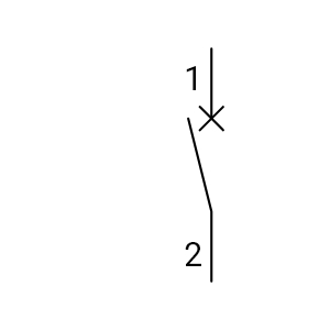
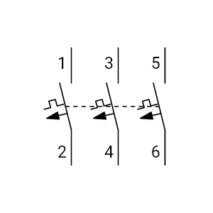
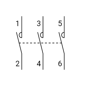
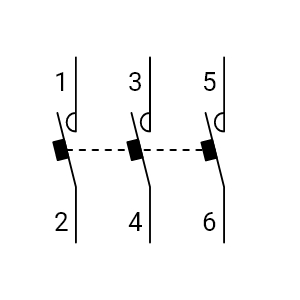
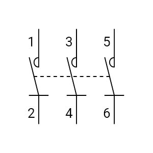
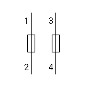
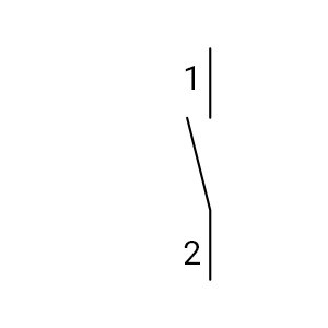
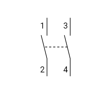
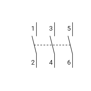
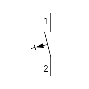
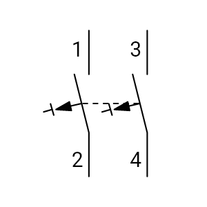
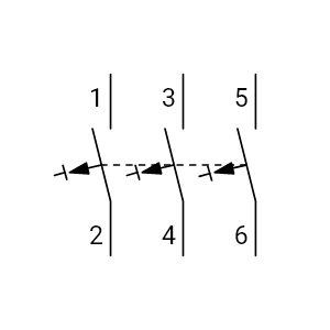
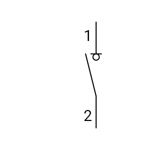
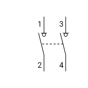
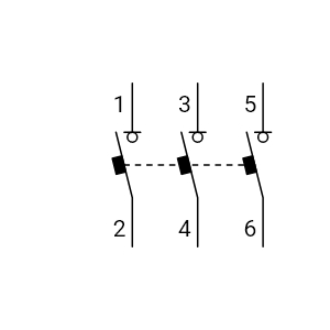
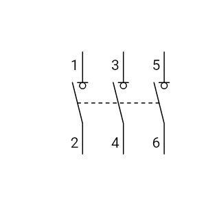
IEC Symbols for Isolators
This symbol represents a circuit breaker that provides disconnection and isolation for the installation downstream. These devices are designed to 'open up' when a certain threshold is reached (e.g., temperature, current, voltage, etc.), cutting off the electrical flow and preventing overcurrents, short circuits, or other electrical faults.
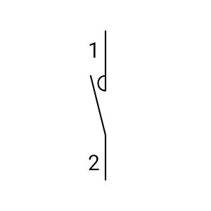
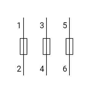
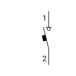
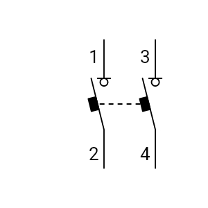
IEC Symbols for Fuses
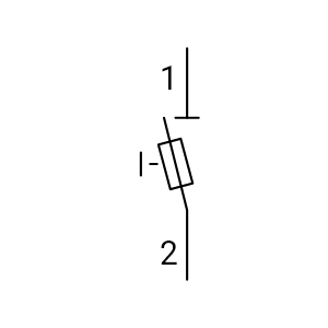
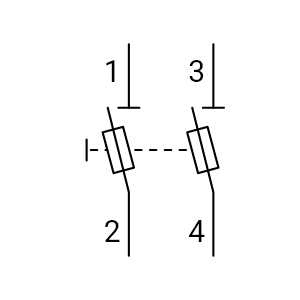
Fuses represent a generic fuse in any electrical circuit. A fuse is used for the protection of any electronic device from an overload or overcurrent. This is achieved by a small metal strip or wire that melts when exposed to a high current/voltage, opening the circuit and blocking the flow of faulty currents.
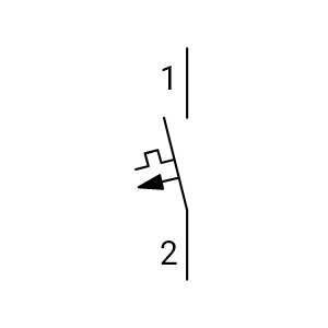
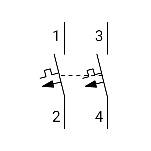
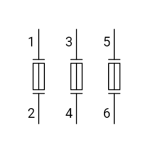
IEC Symbols for Contactors
A contactor is an electrical device used to switch an electrical circuit on or off. While similar in function to a relay, a contactor is primarily used in electronics with a high current carrying capacity, while a relay is used for those with a lower carrying capacity. As such, contactors are commonly utilized to control electric motors due to their high current load.
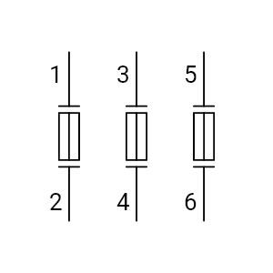
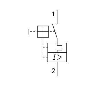
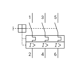
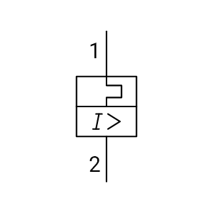
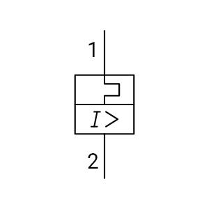
IEC Symbols for Overloads
An overload switch or relay is a device that prevents electrical equipment from overheating and getting damaged due to excessive current, ensuring longer equipment life. When the device detects a current/voltage above the threshold, it will 'open up', cutting the electrical flow and preventing an overcurrent.
Enhance Your Schematic Drawings With Capital X Panel Designer!
Manually drawing and designing IEC symbols for isolators, fuses, contactors, and overloads can be difficult and time-consuming. Fortunately, you can skip the hassle entirely with Capital X Panel Designer! This CAD software provides you with an extensive library of pre-made IEC symbols that you can simply drag and drop into your electrical drawing schematic. Best of all, Capital X Panel Designer is easy to use, ensuring that you can quickly update your schematics to match current plan designs.
Learn more about how to generate electrical symbols automatically.

- JIC / NFPA Sample Drawing
- IEC 60617 Sample Drawing
- P&ID PIP Sample Drawing
- Hydraulic Sample Drawing
- Pneumatic Sample Drawing
- ABB
- AC500 PLC COMM INT Modules
- AC500 PLC COMM INT Modules - Layout
- AC500 PLC COMM Modules
- AC500 PLC COMM Modules - Layout
- AC500 PLC Condition Monitoring Modules
- AC500 PLC Condition Monitoring Modules - Layout
- AC500 PLC CPU Modules
- AC500 PLC CPU Modules - Layout
- AC500 S500 PLC AIO Modules
- AC500 S500 PLC AIO Modules - Layout
- AC500 S500 PLC DIO Modules
- AC500 S500 PLC DIO Modules - Layout
- AC500 S500 PLC Special I/O Modules
- AC500 S500 PLC Special I/O Modules - Layout
- AC500-eco PLC AIO Modules
- AC500-eco PLC AIO Modules - Layout
- AC500-eco PLC CPU Modules
- AC500-eco PLC CPU Modules - Layout
- AC500-eco PLC DIO Modules
- AC500-eco PLC DIO Modules - Layout
- AC500-S PLC AIO Modules
- AC500-S PLC AIO Modules - Layout
- AC500-S PLC CPU Modules
- AC500-S PLC CPU Modules - Layout
- AC500-S PLC DIO Modules
- AC500-S PLC DIO Modules - Layout
- AC500-XC PLC AIO Modules
- AC500-XC PLC AIO Modules - Layout
- AC500-XC PLC COMM INT Modules
- AC500-XC PLC COMM INT Modules - Layout
- AC500-XC PLC COMM Modules
- AC500-XC PLC COMM Modules - Layout
- AC500-XC PLC CPU Modules
- AC500-XC PLC CPU Modules - Layout
- AC500-XC PLC DIO Modules
- AC500-XC PLC DIO Modules - Layout
- AC500-XC PLC Special I/O Modules
- AC500-XC PLC Special I/O Modules - Layout
- Automation brands
- Avatars
- Comments
- Computers and Network
- Do-more
- BRX 10 PLC MPU Modules
- BRX 10 PLC MPU Modules - Layout
- BRX 10E PLC MPU Modules
- BRX 10E PLC MPU Modules - Layout
- BRX 18 PLC MPU Modules
- BRX 18 PLC MPU Modules - Layout
- BRX 18E PLC MPU Modules
- BRX 18E PLC MPU Modules - Layout
- BRX 36 PLC MPU Modules
- BRX 36 PLC MPU Modules - Layout
- BRX 36E PLC MPU Modules
- BRX 36E PLC MPU Modules - Layout
- BRX ME PLC MPU Modules
- BRX ME PLC MPU Modules - Layout
- BRX PLC AIO Modules
- BRX PLC AIO Modules - Layout
- BRX PLC COMM Modules
- BRX PLC COMM Modules - Layout
- BRX PLC DIO Modules
- BRX PLC DIO Modules - Layout
- BRX PLC Special Modules
- BRX PLC Special Modules - Layout
- H2 PLC AC I/O Modules
- H2 PLC AC I/O Modules - Layout
- H2 PLC AC/DC I/O Relay Modules
- H2 PLC AC/DC I/O Relay Modules - Layout
- H2 PLC AIO Modules
- H2 PLC AIO Modules - Layout
- H2 PLC COMM Modules
- H2 PLC COMM Modules - Layout
- H2 PLC CPU Modules
- H2 PLC CPU Modules - Layout
- H2 PLC DC I/O Modules
- H2 PLC DC I/O Modules - Layout
- H2 PLC Ethernet Remote Modules
- H2 PLC Ethernet Remote Modules - Layout
- H2 PLC Special Modules
- H2 PLC Special Modules - Layout
- T1H PLC AC I/O Modules
- T1H PLC AC I/O Modules - Layout
- T1H PLC AC/DC I/O Relay Modules
- T1H PLC AC/DC I/O Relay Modules - Layout
- T1H PLC AIO Modules
- T1H PLC AIO Modules - Layout
- T1H PLC CPU Modules
- T1H PLC CPU Modules - Layout
- T1H PLC DC I/O Modules
- T1H PLC DC I/O Modules - Layout
- T1H PLC Power Supply Modules
- T1H PLC Power Supply Modules - Layout
- T1H PLC Special I/O Modules
- T1H PLC Special I/O Modules - Layout
- Electronic Symbols
- Flow Chart
- Gauge and Meters
- Hitachi
- Micro EHV+ PLC AIO Modules
- Micro EHV+ PLC AIO Modules - Layout
- Micro EHV+ PLC Basic Modules
- Micro EHV+ PLC Basic Modules - Layout
- Micro EHV+ PLC DIO Modules
- Micro EHV+ PLC DIO Modules - Layout
- Micro EHV+ PLC RTD Modules
- Micro EHV+ PLC RTD Modules - Layout
- Micro EHV+ PLC Thermocouple Modules - Layout
- Micro EHV+ PLC, Thermocouple Modules
- Honeywell
- ControlEdge PLC AIO Modules
- ControlEdge PLC AIO Modules - Layout
- ControlEdge PLC COMM Modules
- ControlEdge PLC COMM Modules - Layout
- ControlEdge PLC CPU Modules
- ControlEdge PLC CPU Modules - Layout
- ControlEdge PLC DIO Modules
- ControlEdge PLC DIO Modules - Layout
- ControlEdge PLC Power Modules
- ControlEdge PLC Power Modules - Layout
- ControlEdge PLC UIO Modules
- ControlEdge PLC UIO Modules - Layout
- MasterLogic ML200 PLC AIO Modules
- MasterLogic ML200 PLC AIO Modules - Layout
- MasterLogic ML200 PLC COMM Modules
- MasterLogic ML200 PLC COMM Modules - Layout
- MasterLogic ML200 PLC CPU Modules
- MasterLogic ML200 PLC CPU Modules - Layout
- MasterLogic ML200 PLC DIO Modules
- MasterLogic ML200 PLC DIO Modules - Layout
- MasterLogic ML200 PLC Power Modules
- MasterLogic ML200 PLC Power Modules - Layout
- MasterLogic ML50 PLC AIO Modules
- MasterLogic ML50 PLC AIO Modules - Layout
- MasterLogic ML50 PLC Base Modules
- MasterLogic ML50 PLC Base Modules - Layout
- MasterLogic ML50 PLC COMM Modules
- MasterLogic ML50 PLC COMM Modules - Layout
- MasterLogic ML50 PLC DIO Modules
- MasterLogic ML50 PLC DIO Modules - Layout
- Hydraulic
- IEC 60617
- IEC Isolators, Disconnectors, Fuses, Contactors, Overloads
- IEC Power, Meters, Transformers, Motors
- IEC Symbols
- ISO 1219 Fluidic
- JIC / NFPA Symbols
- Koyo
- DirectLOGIC 05/06 PLC AIO Modules
- DirectLOGIC 05/06 PLC AIO Modules - Layout
- DirectLOGIC 05/06 PLC CPU Modules
- DirectLOGIC 05/06 PLC CPU Modules - Layout
- DirectLOGIC 05/06 PLC DIO Modules
- DirectLOGIC 05/06 PLC DIO Modules - Layout
- DirectLOGIC 05/06 PLC Special Modules
- DirectLOGIC 05/06 PLC Special Modules - Layout
- DirectLOGIC 205 PLC AIO Modules
- DirectLOGIC 205 PLC AIO Modules - Layout
- DirectLOGIC 205 PLC CPU Modules
- DirectLOGIC 205 PLC CPU Modules - Layout
- DirectLOGIC 205 PLC DIO Modules
- DirectLOGIC 205 PLC DIO Modules - Layout
- DirectLOGIC 205 PLC Special Modules
- DirectLOGIC 205 PLC Special Modules - Layout
- DirectLOGIC 405 PLC AIO Modules
- DirectLOGIC 405 PLC AIO Modules - Layout
- DirectLOGIC 405 PLC CPU Modules
- DirectLOGIC 405 PLC CPU Modules - Layout
- DirectLOGIC 405 PLC DIO Modules
- DirectLOGIC 405 PLC DIO Modules - Layout
- DirectLOGIC 405 PLC Special Modules
- DirectLOGIC 405 PLC Special Modules - Layout
- KOSTAC SJ PLC AIO Modules
- KOSTAC SJ PLC AIO Modules - Layout
- KOSTAC SJ PLC CPU Modules
- KOSTAC SJ PLC CPU Modules - Layout
- KOSTAC SJ PLC DIO Modules
- KOSTAC SJ PLC DIO Modules - Layout
- KOSTAC SJ PLC Power Modules
- KOSTAC SJ PLC Power Modules - Layout
- Terminator I/O PLC AIO Modules
- Terminator I/O PLC AIO Modules - Layout
- Terminator I/O PLC DIO Modules
- Terminator I/O PLC DIO Modules - Layout
- Terminator I/O PLC Power Modules
- Terminator I/O PLC Power Modules - Layout
- Layout
- Layout 3D
- Measurement tools
- Mitsubishi Electric
- MELSEC iQ-F PLC AIO Modules
- MELSEC iQ-F PLC AIO Modules - Layout
- MELSEC iQ-F PLC COMM Modules
- MELSEC iQ-F PLC COMM Modules - Layout
- MELSEC iQ-F PLC Counter Modules
- MELSEC iQ-F PLC Counter Modules - Layout
- MELSEC iQ-F PLC CPU Modules
- MELSEC iQ-F PLC CPU Modules - Layout
- MELSEC iQ-F PLC DIO Modules
- MELSEC iQ-F PLC DIO Modules - Layout
- MELSEC iQ-F PLC Motion Modules
- MELSEC iQ-F PLC Motion Modules - Layout
- MELSEC iQ-F PLC Pulse Modules
- MELSEC iQ-F PLC Pulse Modules - Layout
- MELSEC iQ-R PLC AIO Modules
- MELSEC iQ-R PLC AIO Modules - Layout
- MELSEC iQ-R PLC COMM Modules
- MELSEC iQ-R PLC COMM Modules - Layout
- MELSEC iQ-R PLC Counter Modules
- MELSEC iQ-R PLC Counter Modules - Layout
- MELSEC iQ-R PLC CPU Modules
- MELSEC iQ-R PLC CPU Modules - Layout
- MELSEC iQ-R PLC DIO Modules
- MELSEC iQ-R PLC DIO Modules - Layout
- MELSEC iQ-R PLC Motion Modules
- MELSEC iQ-R PLC Motion Modules - Layout
- MELSEC iQ-R PLC Positioning Modules
- MELSEC iQ-R PLC Positioning Modules - Layout
- MELSEC iQ-R PLC Pulse Modules
- MELSEC iQ-R PLC Pulse Modules - Layout
- MELSEC iQ-R PLC Technology Modules
- MELSEC iQ-R PLC Technology Modules - Layout
- MELSEC-F FX3G PLC CPU Modules
- MELSEC-F FX3G PLC CPU Modules - Layout
- MELSEC-F FX3GC PLC CPU Modules
- MELSEC-F FX3GC PLC CPU Modules - Layout
- MELSEC-F FX3S PLC CPU Modules
- MELSEC-F FX3S PLC CPU Modules - Layout
- MELSEC-F FX3U PLC CPU Modules
- MELSEC-F FX3U PLC CPU Modules - Layout
- MELSEC-F FX3UC PLC CPU Modules
- MELSEC-F FX3UC PLC CPU Modules - Layout
- MELSEC-F PLC AIO Modules
- MELSEC-F PLC AIO Modules - Layout
- MELSEC-F PLC COMM Modules
- MELSEC-F PLC COMM Modules - Layout
- MELSEC-F PLC Counter Modules
- MELSEC-F PLC Counter Modules - Layout
- MELSEC-F PLC DIO Modules
- MELSEC-F PLC DIO Modules - Layout
- MELSEC-F PLC Positioning Modules
- MELSEC-F PLC Positioning Modules - Layout
- MELSEC-L PLC AIO Modules
- MELSEC-L PLC AIO Modules - Layout
- MELSEC-L PLC COMM Modules
- MELSEC-L PLC COMM Modules - Layout
- MELSEC-L PLC Counter Modules
- MELSEC-L PLC Counter Modules - Layout
- MELSEC-L PLC CPU Modules
- MELSEC-L PLC CPU Modules - Layout
- MELSEC-L PLC DIO Modules
- MELSEC-L PLC DIO Modules - Layout
- MELSEC-L PLC Motion Modules
- MELSEC-L PLC Motion Modules - Layout
- MELSEC-L PLC Positioning Modules
- MELSEC-L PLC Positioning Modules - Layout
- MELSEC-L PLC Power Modules
- MELSEC-L PLC Power Modules - Layout
- MELSEC-Q PLC AIO Modules
- MELSEC-Q PLC AIO Modules - Layout
- MELSEC-Q PLC Counter Modules
- MELSEC-Q PLC Counter Modules - Layout
- MELSEC-Q PLC CPU Modules
- MELSEC-Q PLC CPU Modules - Layout
- MELSEC-Q PLC DIO Modules
- MELSEC-Q PLC DIO Modules - Layout
- MELSEC-Q PLC Motion Modules
- MELSEC-Q PLC Motion Modules - Layout
- MELSEC-Q PLC Positioning Modules
- MELSEC-Q PLC Positioning Modules - Layout
- MELSEC-Q PLC Pulse Modules
- MELSEC-Q PLC Pulse Modules - Layout
- MELSEC-QS PLC COMM Modules
- MELSEC-QS PLC COMM Modules - Layout
- MELSEC-QS PLC CPU Modules
- MELSEC-QS PLC CPU Modules - Layout
- MELSEC-QS PLC Power Modules
- MELSEC-QS PLC Power Modules - Layout
- Omron
- CJ PLC Basic I/O Modules
- CJ PLC Basic I/O Modules - Layout
- CJ PLC COMM Modules
- CJ PLC COMM Modules - Layout
- CJ PLC Interface Modules
- CJ PLC Interface Modules - Layout
- CJ PLC Power Modules
- CJ PLC Power Modules - Layout
- CJ PLC Special Modules
- CJ PLC Special Modules - Layout
- CK3M PLC CPU Modules
- CK3M PLC CPU Modules - Layout
- CK3W PLC AIO Modules
- CK3W PLC AIO Modules - Layout
- CK3W PLC Axial Interface Modules
- CK3W PLC Axial Interface Modules - Layout
- CK3W PLC DIO Modules
- CK3W PLC DIO Modules - Layout
- CK3W PLC Encoder Modules
- CK3W PLC Encoder Modules - Layout
- CK3W PLC Laser Interface Modules
- CK3W PLC Laser Interface Modules - Layout
- CK3W PLC Power Modules
- CK3W PLC Power Modules - Layout
- CP1E PLC E/ES CPU Modules
- CP1E PLC E/ES CPU Modules - Layout
- CP1E PLC N/NA CPU Modules
- CP1E PLC N/NA CPU Modules - Layout
- CP1E PLC NS/NS1 CPU Modules
- CP1E PLC NS/NS1 CPU Modules - Layout
- CP1H PLC CPU Modules
- CP1H PLC CPU Modules - Layout
- CP1L PLC CPU Modules
- CP1L PLC CPU Modules - Layout
- CP1W PLC AIO Modules
- CP1W PLC AIO Modules - Layout
- CP1W PLC COMM Modules
- CP1W PLC COMM Modules - Layout
- CP1W PLC DIO Modules
- CP1W PLC DIO Modules - Layout
- CP1W PLC TEMP Control Modules
- CP1W PLC TEMP Control Modules - Layout
- CP2E PLC CPU Modules
- CP2E PLC CPU Modules - Layout
- CS1 PLC Basic I/O Modules
- CS1 PLC Basic I/O Modules - Layout
- CS1 PLC COMM Modules
- CS1 PLC COMM Modules - Layout
- CS1 PLC Special Modules
- CS1 PLC Special Modules - Layout
- NJ PLC CPU Modules
- NJ PLC CPU Modules - Layout
- NJ PLC Power Modules
- NJ PLC Power Modules - Layout
- NX PLC AIO Modules
- NX PLC AIO Modules - Layout
- NX PLC COMM Modules
- NX PLC COMM Modules - Layout
- NX PLC DIO Modules
- NX PLC DIO Modules - Layout
- NX PLC Load Cell Modules
- NX PLC Load Cell Modules - Layout
- NX PLC Position Modules
- NX PLC Position Modules - Layout
- NX PLC Power Modules
- NX PLC Power Modules - Layout
- NX PLC RFID Modules
- NX PLC RFID Modules - Layout
- NX PLC Safety CPU Modules
- NX PLC Safety CPU Modules - Layout
- NX PLC Safety I/O Modules
- NX PLC Safety I/O Modules - Layout
- NX PLC TEMP Control Modules
- NX PLC TEMP Control Modules - Layout
- NX1 PLC CPU Modules
- NX1 PLC CPU Modules - Layout
- NX1P2 PLC CPU Modules
- NX1P2 PLC CPU Modules - Layout
- NX7 PLC CPU Modules
- NX7 PLC CPU Modules - Layout
- NX7 PLC Power Modules
- NX7 PLC Power Modules - Layout
- P&ID
- P&ID ISO Equipment
- P&ID ISO Fittings
- P&ID ISO Instruments
- P&ID ISO Pipes and Signal Lines
- P&ID ISO Valves
- P&ID PIP Equipment
- P&ID PIP Fittings
- P&ID PIP Instruments
- P&ID PIP Pipes and Signal Lines
- P&ID PIP Valves
- Pneumatic
- Prefab Circuits
- Productivity
- Productivity 1000 PLC AC I/O Relay Modules
- Productivity 1000 PLC AC I/O Relay Modules - Layout
- Productivity 1000 PLC AIO Modules
- Productivity 1000 PLC AIO Modules - Layout
- Productivity 1000 PLC CPU Modules
- Productivity 1000 PLC CPU Modules - Layout
- Productivity 1000 PLC DC & Combo I/O Modules
- Productivity 1000 PLC DC & Combo I/O Modules - Layout
- Productivity 1000 PLC Motion Modules
- Productivity 1000 PLC Motion Modules - Layout
- Productivity 1000 PLC Power Modules
- Productivity 1000 PLC Power Modules - Layout
- Productivity 1000 PLC Special Modules
- Productivity 1000 PLC Special Modules - Layout
- Productivity 2000 PLC AC I/O Relay Modules
- Productivity 2000 PLC AC I/O Relay Modules - Layout
- Productivity 2000 PLC AIO Modules
- Productivity 2000 PLC AIO Modules - Layout
- Productivity 2000 PLC COMM Modules
- Productivity 2000 PLC COMM Modules - Layout
- Productivity 2000 PLC CPU Modules
- Productivity 2000 PLC CPU Modules - Layout
- Productivity 2000 PLC DC I/O Modules
- Productivity 2000 PLC DC I/O Modules - Layout
- Productivity 2000 PLC Motion Modules
- Productivity 2000 PLC Motion Modules - Layout
- Productivity 2000 PLC Power Modules
- Productivity 2000 PLC Power Modules - Layout
- Productivity 2000 PLC Special Modules
- Productivity 2000 PLC Special Modules - Layout
- Productivity 3000 PLC AC I/O Modules
- Productivity 3000 PLC AC I/O Modules - Layout
- Productivity 3000 PLC AIO Modules
- Productivity 3000 PLC AIO Modules - Layout
- Productivity 3000 PLC COMM Modules
- Productivity 3000 PLC COMM Modules - Layout
- Productivity 3000 PLC CPU Modules
- Productivity 3000 PLC CPU Modules - Layout
- Productivity 3000 PLC DC I/O Modules
- Productivity 3000 PLC DC I/O Modules - Layout
- Productivity 3000 PLC Power Modules
- Productivity 3000 PLC Power Modules - Layout
- Productivity 3000 PLC Special Modules
- Productivity 3000 PLC Special Modules - Layout
- Reports
- Siemens
- LOGO! PLC AIO Modules
- LOGO! PLC AIO Modules - Layout
- LOGO! PLC COMM Modules
- LOGO! PLC COMM Modules - Layout
- LOGO! PLC CPU Modules
- LOGO! PLC CPU Modules - Layout
- LOGO! PLC DIO Modules
- LOGO! PLC DIO Modules - Layout
- LOGO! PLC Power Modules
- LOGO! PLC Power Modules - Layout
- SIMATIC ET200AL PLC AIO Modules
- SIMATIC ET200AL PLC AIO Modules - Layout
- SIMATIC ET200AL PLC DIO Modules
- SIMATIC ET200AL PLC DIO Modules - Layout
- SIMATIC ET200AL PLC Fail-safe Modules
- SIMATIC ET200AL PLC Fail-safe Modules - Layout
- SIMATIC ET200AL PLC Interface Modules
- SIMATIC ET200AL PLC Interface Modules - Layout
- SIMATIC ET200AL PLC IO Link I/O Modules
- SIMATIC ET200AL PLC IO Link I/O Modules - Layout
- SIMATIC ET200ECO PN PLC AIO Modules
- SIMATIC ET200ECO PN PLC AIO Modules - Layout
- SIMATIC ET200ECO PN PLC DIO Modules
- SIMATIC ET200ECO PN PLC DIO Modules - Layout
- SIMATIC ET200ECO PN PLC Fail-safe Modules
- SIMATIC ET200ECO PN PLC Fail-safe Modules - Layout
- SIMATIC ET200ECO PN PLC IO Link Master Modules
- SIMATIC ET200ECO PN PLC IO Link Master Modules - Layout
- SIMATIC ET200iSP PLC AIO Modules
- SIMATIC ET200iSP PLC AIO Modules - Layout
- SIMATIC ET200iSP PLC COMM Modules - Layout
- SIMATIC ET200iSP PLC DIO Modules
- SIMATIC ET200iSP PLC DIO Modules - Layout
- SIMATIC ET200iSP PLC Fail-safe Modules
- SIMATIC ET200iSP PLC Fail-safe Modules - Layout
- SIMATIC ET200iSP PLC Interface Modules
- SIMATIC ET200iSP PLC Interface Modules - Layout
- SIMATIC ET200iSP PLC Power Modules
- SIMATIC ET200iSP PLC Power Modules - Layout
- SIMATIC ET200iSP PLC, COMM Modules
- SIMATIC ET200M PLC Interface Modules
- SIMATIC ET200M PLC Interface Modules - Layout
- SIMATIC ET200MP PLC Interface Modules
- SIMATIC ET200MP PLC Interface Modules - Layout
- SIMATIC ET200MP PLC Power Modules
- SIMATIC ET200MP PLC Power Modules - Layout
- SIMATIC ET200pro PLC AIO Modules
- SIMATIC ET200pro PLC AIO Modules - Layout
- SIMATIC ET200pro PLC COMM Modules
- SIMATIC ET200pro PLC COMM Modules - Layout
- SIMATIC ET200pro PLC CPU Modules
- SIMATIC ET200pro PLC CPU Modules - Layout
- SIMATIC ET200pro PLC DIO Modules
- SIMATIC ET200pro PLC DIO Modules - Layout
- SIMATIC ET200pro PLC Fail-safe Modules
- SIMATIC ET200pro PLC Fail-safe Modules - Layout
- SIMATIC ET200pro PLC Interface Modules
- SIMATIC ET200pro PLC Interface Modules - Layout
- SIMATIC ET200pro PLC Power Modules
- SIMATIC ET200pro PLC Power Modules - Layout
- SIMATIC ET200S PLC AIO Modules
- SIMATIC ET200S PLC AIO Modules - Layout
- SIMATIC ET200S PLC CPU Modules
- SIMATIC ET200S PLC CPU Modules - Layout
- SIMATIC ET200S PLC DIO Modules
- SIMATIC ET200S PLC DIO Modules - Layout
- SIMATIC ET200S PLC Fail-safe Modules
- SIMATIC ET200S PLC Fail-safe Modules - Layout
- SIMATIC ET200S PLC POT DIS Modules
- SIMATIC ET200S PLC POT DIS Modules - Layout
- SIMATIC ET200S PLC Power Modules
- SIMATIC ET200S PLC Power Modules - Layout
- SIMATIC ET200S PLC Technology Modules
- SIMATIC ET200S PLC Technology Modules - Layout
- SIMATIC ET200SP HA PLC AIO Modules
- SIMATIC ET200SP HA PLC AIO Modules - Layout
- SIMATIC ET200SP HA PLC AIO/DIO Modules
- SIMATIC ET200SP HA PLC AIO/DIO Modules - Layout
- SIMATIC ET200SP HA PLC DIO Modules
- SIMATIC ET200SP HA PLC DIO Modules - Layout
- SIMATIC ET200SP HA PLC EX I/O Modules
- SIMATIC ET200SP HA PLC EX I/O Modules - Layout
- SIMATIC ET200SP HA PLC Fail-safe I/O Modules
- SIMATIC ET200SP HA PLC Fail-safe I/O Modules - Layout
- SIMATIC ET200SP HA PLC Interface Modules
- SIMATIC ET200SP HA PLC Interface Modules - Layout
- SIMATIC ET200SP PLC AIO Modules
- SIMATIC ET200SP PLC AIO Modules - Layout
- SIMATIC ET200SP PLC COMM Modules
- SIMATIC ET200SP PLC COMM Modules - Layout
- SIMATIC ET200SP PLC CPU Modules
- SIMATIC ET200SP PLC CPU Modules - Layout
- SIMATIC ET200SP PLC DIO Modules
- SIMATIC ET200SP PLC DIO Modules - Layout
- SIMATIC ET200SP PLC DRIVE Modules
- SIMATIC ET200SP PLC DRIVE Modules - Layout
- SIMATIC ET200SP PLC Fail-safe Modules
- SIMATIC ET200SP PLC Fail-safe Modules - Layout
- SIMATIC ET200SP PLC Power Modules
- SIMATIC ET200SP PLC Power Modules - Layout
- SIMATIC ET200SP PLC TECH Modules - Layout
- SIMATIC ET200SP PLC, TECH Modules
- SIMATIC S7-1200 PLC AIO Modules
- SIMATIC S7-1200 PLC AIO Modules - Layout
- SIMATIC S7-1200 PLC COMM Modules
- SIMATIC S7-1200 PLC COMM Modules - Layout
- SIMATIC S7-1200 PLC CPU Modules
- SIMATIC S7-1200 PLC CPU Modules - Layout
- SIMATIC S7-1200 PLC DIO Modules
- SIMATIC S7-1200 PLC DIO Modules - Layout
- SIMATIC S7-1200 PLC Power Modules
- SIMATIC S7-1200 PLC Power Modules - Layout
- SIMATIC S7-1200 PLC Special Modules
- SIMATIC S7-1200 PLC Special Modules - Layout
- SIMATIC S7-1500 CPU Modules
- SIMATIC S7-1500 PLC AIO Modules
- SIMATIC S7-1500 PLC AIO Modules - Layout
- SIMATIC S7-1500 PLC COMM Modules
- SIMATIC S7-1500 PLC COMM Modules - Layout
- SIMATIC S7-1500 PLC CPU Modules - Layout
- SIMATIC S7-1500 PLC DIO Modules
- SIMATIC S7-1500 PLC DIO Modules - Layout
- SIMATIC S7-1500 PLC Fail-safe Modules
- SIMATIC S7-1500 PLC Fail-safe Modules - Layout
- SIMATIC S7-1500 PLC Power Modules
- SIMATIC S7-1500 PLC Power Modules - Layout
- SIMATIC S7-1500 PLC TECH Modules
- SIMATIC S7-1500 PLC TECH Modules - Layout
- SIMATIC S7-200 PLC AIO Modules
- SIMATIC S7-200 PLC AIO Modules - Layout
- SIMATIC S7-200 PLC COMM Modules
- SIMATIC S7-200 PLC COMM Modules - Layout
- SIMATIC S7-200 PLC CPU Modules
- SIMATIC S7-200 PLC CPU Modules - Layout
- SIMATIC S7-200 PLC DIO Modules
- SIMATIC S7-200 PLC DIO Modules - Layout
- SIMATIC S7-200 PLC Positioning Modules
- SIMATIC S7-200 PLC Positioning Modules - Layout
- SIMATIC S7-300 PLC AIO Modules
- SIMATIC S7-300 PLC AIO Modules - Layout
- SIMATIC S7-300 PLC COMM Modules
- SIMATIC S7-300 PLC COMM Modules - Layout
- SIMATIC S7-300 PLC CPU Modules
- SIMATIC S7-300 PLC CPU Modules - Layout
- SIMATIC S7-300 PLC DIO Modules
- SIMATIC S7-300 PLC DIO Modules - Layout
- SIMATIC S7-300 PLC Ex AIO Modules
- SIMATIC S7-300 PLC Ex AIO Modules - Layout
- SIMATIC S7-300 PLC Ex DIO Modules
- SIMATIC S7-300 PLC Ex DIO Modules - Layout
- SIMATIC S7-300 PLC F-DIO/AIO Modules
- SIMATIC S7-300 PLC F-DIO/AIO Modules - Layout
- SIMATIC S7-300 PLC Function Modules
- SIMATIC S7-300 PLC Function Modules - Layout
- SIMATIC S7-300 PLC Power Modules
- SIMATIC S7-300 PLC Power Modules - Layout
- SIMATIC S7-300 PLC Special Modules
- SIMATIC S7-300 PLC Special Modules - Layout
- SIMATIC S7-400 PLC AIO Modules
- SIMATIC S7-400 PLC AIO Modules - Layout
- SIMATIC S7-400 PLC COMM Modules
- SIMATIC S7-400 PLC COMM Modules - Layout
- SIMATIC S7-400 PLC CPU Modules
- SIMATIC S7-400 PLC CPU Modules - Layout
- SIMATIC S7-400 PLC DIO Modules
- SIMATIC S7-400 PLC DIO Modules - Layout
- SIMATIC S7-400 PLC Function Modules
- SIMATIC S7-400 PLC Function Modules - Layout
- SIMATIC S7-400 PLC Interface Modules
- SIMATIC S7-400 PLC Interface Modules - Layout
- SIMATIC S7-400 PLC Power Modules
- SIMATIC S7-400 PLC Power Modules - Layout
- Single Line Symbols
- Title blocks
- Wires
- announciators
- auxilliary contacts
- batteries
- brakes & clutches
- cam switches
- capacitors
- circuit breakers
- connectors
- contactors
- counters
- diacs & triacs
- diodes
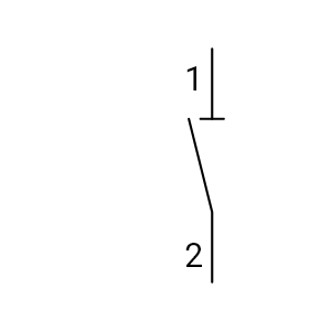
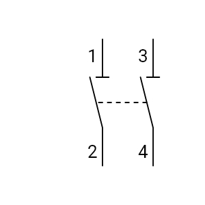
- disconnectors
- emergency switches
- flow sensors
- foot switches
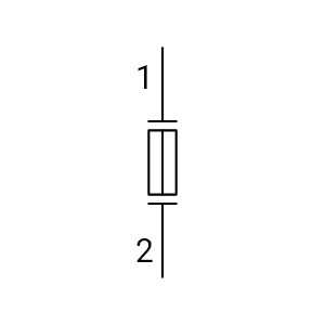
- fuses
- heaters
- home and building
- hydraulic miscellaneous
- inductors
- layout
- level sensors
- limit switches
- meters
- miscellaneous
- motors
- optocouplers
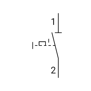
- overload trips
- panels
- photoelectric sensors
- P&ID
- pilot lights
- pneumatic miscellaneous
- power supplies
- Prefabricated circuits
- Pressure sensors
- Programmable Logic Controllers (PLC)
- proximity sensors
- pull buttons
- push buttons
- relays
- resistors
- selector switches
- solenoid valves
- temperature sensors & controllers
- terminal block
- thermistors
- timers
- transformers
- transistors


Circuit Breaker Thermal & Magnetic 1P

Circuit Breaker Thermal & Magnetic 2P

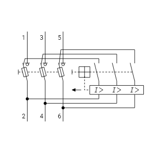
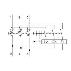
Circuit Breaker Thermal & Magnetic 3P


Contactor 3P - Automatic Tripping

Contactor 3P - Semiconductor


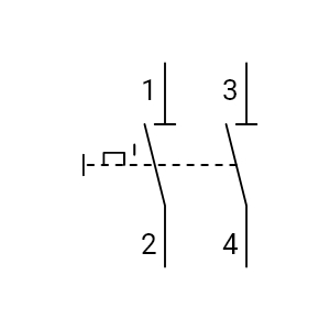
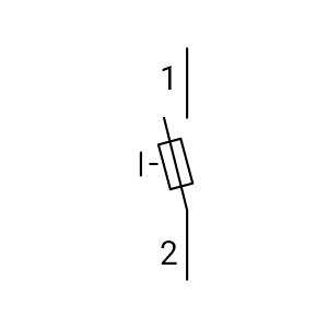
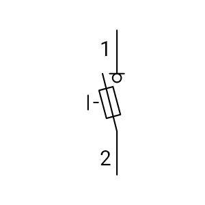
Disconnector/ Isolator 1P - with Lock
Disconnector/ Isolator 1P - with Lock
Disconnector/ Isolator 1P - with Lock


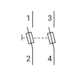
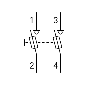
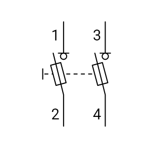
Disconnector/Isolator 2P - with Lock
Disconnector/Isolator 2P - with Lock
Disconnector/Isolator 2P - with Lock

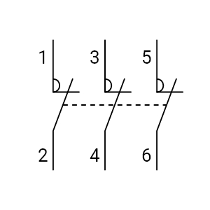
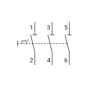
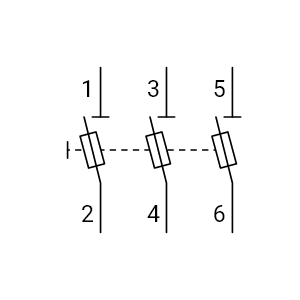
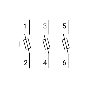
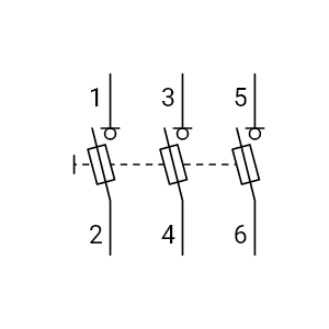
Disconnector/Isolator 3P - with Lock
Disconnector/Isolator 3P - with Lock
Disconnector/Isolator 3P - with Lock


Fuse 1P - Low Voltage High Breaking Capacity
Fuse 1P - Low Voltage High Breaking Capacity
Fuse 1P - Low Voltage High Breaking Capacity


Fuse 2P - Low Voltage High Breaking Capacity
Fuse 2P - Low Voltage High Breaking Capacity
Fuse 2P - Low Voltage High Breaking Capacity


Fuse 3P - Low Voltage High Breaking Capacity
Fuse 3P - Low Voltage High Breaking Capacity
Fuse 3P - Low Voltage High Breaking Capacity

Fuse Disconnector w Motor Circuit Breaker 1P
Fuse Disconnector with Motor Circuit Breaker 1P
Fuse Disconnector w Motor Circuit Breaker 1P

Fuse Disconnector w Motor Circuit Breaker 2P
Fuse Disconnector w Motor Circuit Breaker 2P
Fuse Disconnector w Motor Circuit Breaker 2P

Fuse Disconnector w Motor Circuit Breaker 3P
Fuse Disconnector w Motor Circuit Breaker 3P
Fuse Disconnector w Motor Circuit Breaker 3P

Fuse Disconnector/ Isolator 1P

Fuse Disconnector/Isolator 2P

Fuse Disconnector/Isolator 3P


Fuse Switch Disconnector 1P

Fuse Switch Disconnector 2P

Fuse Switch Disconnector 3P


Residual Current Circuit Breaker 1P

Residual Current Circuit Breaker 2P

Residual Current Circuit Breaker 3P


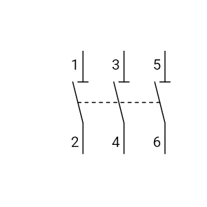
Switch Disconnector 1P - Automatic Tripping
Switch Disconnector 1P - Automatic Tripping
Switch Disconnector 1P - Automatic Tripping


Switch Disconnector 2P - Automatic Tripping
Switch Disconnector 2P - Automatic Tripping
Switch Disconnector 2P - Automatic Tripping

Switch Disconnector 3P - Automatic Tripping
Switch Disconnector 3P - Automatic Tripping
Switch Disconnector 3P - Automatic Tripping


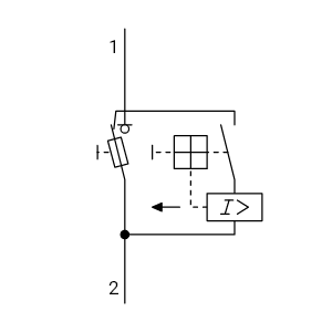
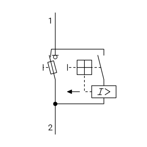
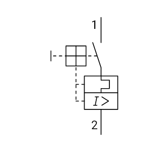
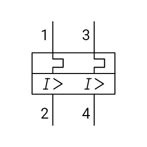
Thermal / Current Overload 1P

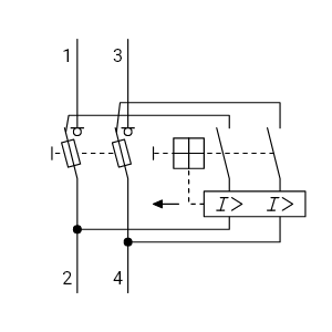
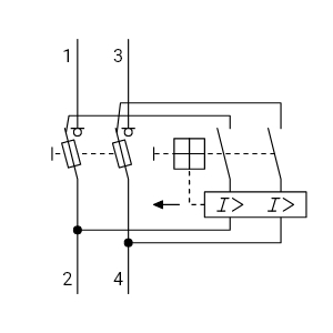
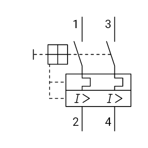
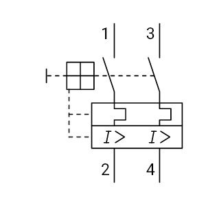
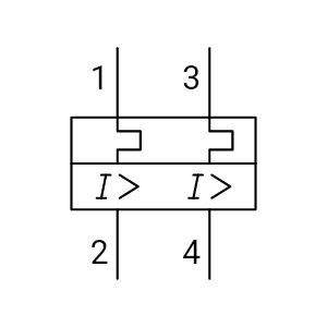
Thermal / Current Overload 2P
