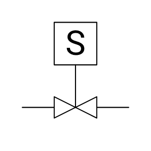
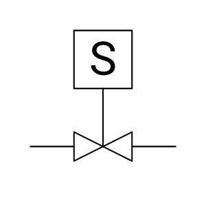
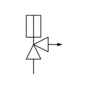
Solenoid Valve
P&ID PIP Valves
Tip: Whether you’re looking for hydraulic solenoid valve symbols or pneumatic solenoid valve symbols, Capital X Panel Designer has them all! Browse through a selection of ready-made solenoid valve symbols, select the one you need for your electrical schematic drawing and then simply drag and drop it into your design.
Sign up for the 30-day FREE Electrical Schematic Software trial and experience a boost in your workflow productivity!
Learn more about how to automatically generate electrical symbols now.
Show more
What is the Function of a Solenoid Valve Symbol?
A solenoid valve symbol is a simplified representation of a solenoid valve component, used to indicate its position and purpose in a schematic diagram visually. The solenoid valve is a device that controls the flow of fluids using an electric current.
Types of Solenoid Valve Symbols
Solenoid valves differ in the characteristics of the electric current they use, the strength of the magnetic field they generate, their regulatory mechanism, and the type and characteristics of the fluid they control. As such, different symbols are used to represent each type of solenoid valve:
2/2 Way Solenoid Valve Symbol
The majority of solenoid valves are normally closed 2/2-way valves. The symbol is comprised of two adjacent squares representing the two states of the valve. The ‘T’ symbol in the right-hand square indicates that the valve is normally closed, while the arrow in the left-hand square points in the direction of fluid flow while the valve is actuated. Lastly, the coil on the left-hand side and the spring on the right-hand side indicate the means of pilot control and return control for the valve operation, respectively.
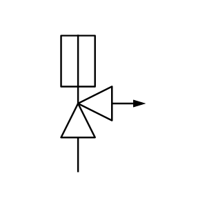
3/2 Way Solenoid Valve Symbol
A 3/2-way solenoid valve has two positions and three connection ports, allowing a single valve can be used to control the fluid flow in two circuits. These valves can be used for multiple applications, such as switching between two circuits or actuating a hydraulic cylinder. Similar to the 2/2 way solenoid valve, this symbol has representations of the coil on the left-hand side and the spring on the right-hand side to indicate the means of pilot control and return control for the valve operation, respectively.
What Solenoid Valve Symbols Look Like in a P&ID
A piping and instrumentation diagram (P&ID) is a detailed graphical representation of a process that includes both the hardware and software necessary to design, assemble, and operate the system. It is similar in design to the circuit diagram of an electronic circuit, using symbols to indicate the components and their locations.
Compared to those used in fluid power diagrams, these symbols are simpler and less detailed. Arrows are used to demonstrate the direction of fluid flow in 3-way and 4-way valves, indicating de-energized flow paths that give fluid flow direction when the valve is at rest (non-actuated).
The various labels are:
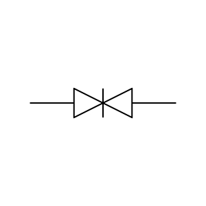
- A: Two-way on-off solenoid valve
- B: Angle on-off solenoid valve
- C: Three-way on-off solenoid valve
- D: Four-way plug or ball on-off solenoid valve
- E: Four-way, five-ported on-off solenoid valve
Standardization of Symbols
The International Society Of Automation (ISA) enforces a strict set of standards to ensure uniformity in P&ID symbols. Regardless, there are different ways to represent valves, such as using text descriptions, a unique model called the part number, a tag number, which is a specific component in the system, and a detailed legend.
Skip the Drawing Process With Capital X Panel Designer!
Drawing a solenoid valve symbol manually is a time-consuming process. With Capital X Panel Designer, you can skip the procedure entirely by simply browsing through our library of pre-made symbols and then dragging and dropping them into your schematic. This easy-to-use CAD software will provide a huge boost to your productivity.
Learn more about how to generate electrical symbols automatically.

- JIC / NFPA Sample Drawing
- IEC 60617 Sample Drawing
- P&ID PIP Sample Drawing
- Hydraulic Sample Drawing
- Pneumatic Sample Drawing
- ABB
- AC500 PLC COMM INT Modules
- AC500 PLC COMM INT Modules - Layout
- AC500 PLC COMM Modules
- AC500 PLC COMM Modules - Layout
- AC500 PLC Condition Monitoring Modules
- AC500 PLC Condition Monitoring Modules - Layout
- AC500 PLC CPU Modules
- AC500 PLC CPU Modules - Layout
- AC500 S500 PLC AIO Modules
- AC500 S500 PLC AIO Modules - Layout
- AC500 S500 PLC DIO Modules
- AC500 S500 PLC DIO Modules - Layout
- AC500 S500 PLC Special I/O Modules
- AC500 S500 PLC Special I/O Modules - Layout
- AC500-eco PLC AIO Modules
- AC500-eco PLC AIO Modules - Layout
- AC500-eco PLC CPU Modules
- AC500-eco PLC CPU Modules - Layout
- AC500-eco PLC DIO Modules
- AC500-eco PLC DIO Modules - Layout
- AC500-S PLC AIO Modules
- AC500-S PLC AIO Modules - Layout
- AC500-S PLC CPU Modules
- AC500-S PLC CPU Modules - Layout
- AC500-S PLC DIO Modules
- AC500-S PLC DIO Modules - Layout
- AC500-XC PLC AIO Modules
- AC500-XC PLC AIO Modules - Layout
- AC500-XC PLC COMM INT Modules
- AC500-XC PLC COMM INT Modules - Layout
- AC500-XC PLC COMM Modules
- AC500-XC PLC COMM Modules - Layout
- AC500-XC PLC CPU Modules
- AC500-XC PLC CPU Modules - Layout
- AC500-XC PLC DIO Modules
- AC500-XC PLC DIO Modules - Layout
- AC500-XC PLC Special I/O Modules
- AC500-XC PLC Special I/O Modules - Layout
- Automation brands
- Avatars
- Comments
- Computers and Network
- Do-more
- BRX 10 PLC MPU Modules
- BRX 10 PLC MPU Modules - Layout
- BRX 10E PLC MPU Modules
- BRX 10E PLC MPU Modules - Layout
- BRX 18 PLC MPU Modules
- BRX 18 PLC MPU Modules - Layout
- BRX 18E PLC MPU Modules
- BRX 18E PLC MPU Modules - Layout
- BRX 36 PLC MPU Modules
- BRX 36 PLC MPU Modules - Layout
- BRX 36E PLC MPU Modules
- BRX 36E PLC MPU Modules - Layout
- BRX ME PLC MPU Modules
- BRX ME PLC MPU Modules - Layout
- BRX PLC AIO Modules
- BRX PLC AIO Modules - Layout
- BRX PLC COMM Modules
- BRX PLC COMM Modules - Layout
- BRX PLC DIO Modules
- BRX PLC DIO Modules - Layout
- BRX PLC Special Modules
- BRX PLC Special Modules - Layout
- H2 PLC AC I/O Modules
- H2 PLC AC I/O Modules - Layout
- H2 PLC AC/DC I/O Relay Modules
- H2 PLC AC/DC I/O Relay Modules - Layout
- H2 PLC AIO Modules
- H2 PLC AIO Modules - Layout
- H2 PLC COMM Modules
- H2 PLC COMM Modules - Layout
- H2 PLC CPU Modules
- H2 PLC CPU Modules - Layout
- H2 PLC DC I/O Modules
- H2 PLC DC I/O Modules - Layout
- H2 PLC Ethernet Remote Modules
- H2 PLC Ethernet Remote Modules - Layout
- H2 PLC Special Modules
- H2 PLC Special Modules - Layout
- T1H PLC AC I/O Modules
- T1H PLC AC I/O Modules - Layout
- T1H PLC AC/DC I/O Relay Modules
- T1H PLC AC/DC I/O Relay Modules - Layout
- T1H PLC AIO Modules
- T1H PLC AIO Modules - Layout
- T1H PLC CPU Modules
- T1H PLC CPU Modules - Layout
- T1H PLC DC I/O Modules
- T1H PLC DC I/O Modules - Layout
- T1H PLC Power Supply Modules
- T1H PLC Power Supply Modules - Layout
- T1H PLC Special I/O Modules
- T1H PLC Special I/O Modules - Layout
- Electronic Symbols
- Flow Chart
- Gauge and Meters
- Hitachi
- Micro EHV+ PLC AIO Modules
- Micro EHV+ PLC AIO Modules - Layout
- Micro EHV+ PLC Basic Modules
- Micro EHV+ PLC Basic Modules - Layout
- Micro EHV+ PLC DIO Modules
- Micro EHV+ PLC DIO Modules - Layout
- Micro EHV+ PLC RTD Modules
- Micro EHV+ PLC RTD Modules - Layout
- Micro EHV+ PLC Thermocouple Modules - Layout
- Micro EHV+ PLC, Thermocouple Modules
- Honeywell
- ControlEdge PLC AIO Modules
- ControlEdge PLC AIO Modules - Layout
- ControlEdge PLC COMM Modules
- ControlEdge PLC COMM Modules - Layout
- ControlEdge PLC CPU Modules
- ControlEdge PLC CPU Modules - Layout
- ControlEdge PLC DIO Modules
- ControlEdge PLC DIO Modules - Layout
- ControlEdge PLC Power Modules
- ControlEdge PLC Power Modules - Layout
- ControlEdge PLC UIO Modules
- ControlEdge PLC UIO Modules - Layout
- MasterLogic ML200 PLC AIO Modules
- MasterLogic ML200 PLC AIO Modules - Layout
- MasterLogic ML200 PLC COMM Modules
- MasterLogic ML200 PLC COMM Modules - Layout
- MasterLogic ML200 PLC CPU Modules
- MasterLogic ML200 PLC CPU Modules - Layout
- MasterLogic ML200 PLC DIO Modules
- MasterLogic ML200 PLC DIO Modules - Layout
- MasterLogic ML200 PLC Power Modules
- MasterLogic ML200 PLC Power Modules - Layout
- MasterLogic ML50 PLC AIO Modules
- MasterLogic ML50 PLC AIO Modules - Layout
- MasterLogic ML50 PLC Base Modules
- MasterLogic ML50 PLC Base Modules - Layout
- MasterLogic ML50 PLC COMM Modules
- MasterLogic ML50 PLC COMM Modules - Layout
- MasterLogic ML50 PLC DIO Modules
- MasterLogic ML50 PLC DIO Modules - Layout
- Hydraulic
- IEC 60617
- IEC Isolators, Disconnectors, Fuses, Contactors, Overloads
- IEC Power, Meters, Transformers, Motors
- IEC Symbols
- ISO 1219 Fluidic
- JIC / NFPA Symbols
- Koyo
- DirectLOGIC 05/06 PLC AIO Modules
- DirectLOGIC 05/06 PLC AIO Modules - Layout
- DirectLOGIC 05/06 PLC CPU Modules
- DirectLOGIC 05/06 PLC CPU Modules - Layout
- DirectLOGIC 05/06 PLC DIO Modules
- DirectLOGIC 05/06 PLC DIO Modules - Layout
- DirectLOGIC 05/06 PLC Special Modules
- DirectLOGIC 05/06 PLC Special Modules - Layout
- DirectLOGIC 205 PLC AIO Modules
- DirectLOGIC 205 PLC AIO Modules - Layout
- DirectLOGIC 205 PLC CPU Modules
- DirectLOGIC 205 PLC CPU Modules - Layout
- DirectLOGIC 205 PLC DIO Modules
- DirectLOGIC 205 PLC DIO Modules - Layout
- DirectLOGIC 205 PLC Special Modules
- DirectLOGIC 205 PLC Special Modules - Layout
- DirectLOGIC 405 PLC AIO Modules
- DirectLOGIC 405 PLC AIO Modules - Layout
- DirectLOGIC 405 PLC CPU Modules
- DirectLOGIC 405 PLC CPU Modules - Layout
- DirectLOGIC 405 PLC DIO Modules
- DirectLOGIC 405 PLC DIO Modules - Layout
- DirectLOGIC 405 PLC Special Modules
- DirectLOGIC 405 PLC Special Modules - Layout
- KOSTAC SJ PLC AIO Modules
- KOSTAC SJ PLC AIO Modules - Layout
- KOSTAC SJ PLC CPU Modules
- KOSTAC SJ PLC CPU Modules - Layout
- KOSTAC SJ PLC DIO Modules
- KOSTAC SJ PLC DIO Modules - Layout
- KOSTAC SJ PLC Power Modules
- KOSTAC SJ PLC Power Modules - Layout
- Terminator I/O PLC AIO Modules
- Terminator I/O PLC AIO Modules - Layout
- Terminator I/O PLC DIO Modules
- Terminator I/O PLC DIO Modules - Layout
- Terminator I/O PLC Power Modules
- Terminator I/O PLC Power Modules - Layout
- Layout
- Layout 3D
- Measurement tools
- Mitsubishi Electric
- MELSEC iQ-F PLC AIO Modules
- MELSEC iQ-F PLC AIO Modules - Layout
- MELSEC iQ-F PLC COMM Modules
- MELSEC iQ-F PLC COMM Modules - Layout
- MELSEC iQ-F PLC Counter Modules
- MELSEC iQ-F PLC Counter Modules - Layout
- MELSEC iQ-F PLC CPU Modules
- MELSEC iQ-F PLC CPU Modules - Layout
- MELSEC iQ-F PLC DIO Modules
- MELSEC iQ-F PLC DIO Modules - Layout
- MELSEC iQ-F PLC Motion Modules
- MELSEC iQ-F PLC Motion Modules - Layout
- MELSEC iQ-F PLC Pulse Modules
- MELSEC iQ-F PLC Pulse Modules - Layout
- MELSEC iQ-R PLC AIO Modules
- MELSEC iQ-R PLC AIO Modules - Layout
- MELSEC iQ-R PLC COMM Modules
- MELSEC iQ-R PLC COMM Modules - Layout
- MELSEC iQ-R PLC Counter Modules
- MELSEC iQ-R PLC Counter Modules - Layout
- MELSEC iQ-R PLC CPU Modules
- MELSEC iQ-R PLC CPU Modules - Layout
- MELSEC iQ-R PLC DIO Modules
- MELSEC iQ-R PLC DIO Modules - Layout
- MELSEC iQ-R PLC Motion Modules
- MELSEC iQ-R PLC Motion Modules - Layout
- MELSEC iQ-R PLC Positioning Modules
- MELSEC iQ-R PLC Positioning Modules - Layout
- MELSEC iQ-R PLC Pulse Modules
- MELSEC iQ-R PLC Pulse Modules - Layout
- MELSEC iQ-R PLC Technology Modules
- MELSEC iQ-R PLC Technology Modules - Layout
- MELSEC-F FX3G PLC CPU Modules
- MELSEC-F FX3G PLC CPU Modules - Layout
- MELSEC-F FX3GC PLC CPU Modules
- MELSEC-F FX3GC PLC CPU Modules - Layout
- MELSEC-F FX3S PLC CPU Modules
- MELSEC-F FX3S PLC CPU Modules - Layout
- MELSEC-F FX3U PLC CPU Modules
- MELSEC-F FX3U PLC CPU Modules - Layout
- MELSEC-F FX3UC PLC CPU Modules
- MELSEC-F FX3UC PLC CPU Modules - Layout
- MELSEC-F PLC AIO Modules
- MELSEC-F PLC AIO Modules - Layout
- MELSEC-F PLC COMM Modules
- MELSEC-F PLC COMM Modules - Layout
- MELSEC-F PLC Counter Modules
- MELSEC-F PLC Counter Modules - Layout
- MELSEC-F PLC DIO Modules
- MELSEC-F PLC DIO Modules - Layout
- MELSEC-F PLC Positioning Modules
- MELSEC-F PLC Positioning Modules - Layout
- MELSEC-L PLC AIO Modules
- MELSEC-L PLC AIO Modules - Layout
- MELSEC-L PLC COMM Modules
- MELSEC-L PLC COMM Modules - Layout
- MELSEC-L PLC Counter Modules
- MELSEC-L PLC Counter Modules - Layout
- MELSEC-L PLC CPU Modules
- MELSEC-L PLC CPU Modules - Layout
- MELSEC-L PLC DIO Modules
- MELSEC-L PLC DIO Modules - Layout
- MELSEC-L PLC Motion Modules
- MELSEC-L PLC Motion Modules - Layout
- MELSEC-L PLC Positioning Modules
- MELSEC-L PLC Positioning Modules - Layout
- MELSEC-L PLC Power Modules
- MELSEC-L PLC Power Modules - Layout
- MELSEC-Q PLC AIO Modules
- MELSEC-Q PLC AIO Modules - Layout
- MELSEC-Q PLC Counter Modules
- MELSEC-Q PLC Counter Modules - Layout
- MELSEC-Q PLC CPU Modules
- MELSEC-Q PLC CPU Modules - Layout
- MELSEC-Q PLC DIO Modules
- MELSEC-Q PLC DIO Modules - Layout
- MELSEC-Q PLC Motion Modules
- MELSEC-Q PLC Motion Modules - Layout
- MELSEC-Q PLC Positioning Modules
- MELSEC-Q PLC Positioning Modules - Layout
- MELSEC-Q PLC Pulse Modules
- MELSEC-Q PLC Pulse Modules - Layout
- MELSEC-QS PLC COMM Modules
- MELSEC-QS PLC COMM Modules - Layout
- MELSEC-QS PLC CPU Modules
- MELSEC-QS PLC CPU Modules - Layout
- MELSEC-QS PLC Power Modules
- MELSEC-QS PLC Power Modules - Layout
- Omron
- CJ PLC Basic I/O Modules
- CJ PLC Basic I/O Modules - Layout
- CJ PLC COMM Modules
- CJ PLC COMM Modules - Layout
- CJ PLC Interface Modules
- CJ PLC Interface Modules - Layout
- CJ PLC Power Modules
- CJ PLC Power Modules - Layout
- CJ PLC Special Modules
- CJ PLC Special Modules - Layout
- CK3M PLC CPU Modules
- CK3M PLC CPU Modules - Layout
- CK3W PLC AIO Modules
- CK3W PLC AIO Modules - Layout
- CK3W PLC Axial Interface Modules
- CK3W PLC Axial Interface Modules - Layout
- CK3W PLC DIO Modules
- CK3W PLC DIO Modules - Layout
- CK3W PLC Encoder Modules
- CK3W PLC Encoder Modules - Layout
- CK3W PLC Laser Interface Modules
- CK3W PLC Laser Interface Modules - Layout
- CK3W PLC Power Modules
- CK3W PLC Power Modules - Layout
- CP1E PLC E/ES CPU Modules
- CP1E PLC E/ES CPU Modules - Layout
- CP1E PLC N/NA CPU Modules
- CP1E PLC N/NA CPU Modules - Layout
- CP1E PLC NS/NS1 CPU Modules
- CP1E PLC NS/NS1 CPU Modules - Layout
- CP1H PLC CPU Modules
- CP1H PLC CPU Modules - Layout
- CP1L PLC CPU Modules
- CP1L PLC CPU Modules - Layout
- CP1W PLC AIO Modules
- CP1W PLC AIO Modules - Layout
- CP1W PLC COMM Modules
- CP1W PLC COMM Modules - Layout
- CP1W PLC DIO Modules
- CP1W PLC DIO Modules - Layout
- CP1W PLC TEMP Control Modules
- CP1W PLC TEMP Control Modules - Layout
- CP2E PLC CPU Modules
- CP2E PLC CPU Modules - Layout
- CS1 PLC Basic I/O Modules
- CS1 PLC Basic I/O Modules - Layout
- CS1 PLC COMM Modules
- CS1 PLC COMM Modules - Layout
- CS1 PLC Special Modules
- CS1 PLC Special Modules - Layout
- NJ PLC CPU Modules
- NJ PLC CPU Modules - Layout
- NJ PLC Power Modules
- NJ PLC Power Modules - Layout
- NX PLC AIO Modules
- NX PLC AIO Modules - Layout
- NX PLC COMM Modules
- NX PLC COMM Modules - Layout
- NX PLC DIO Modules
- NX PLC DIO Modules - Layout
- NX PLC Load Cell Modules
- NX PLC Load Cell Modules - Layout
- NX PLC Position Modules
- NX PLC Position Modules - Layout
- NX PLC Power Modules
- NX PLC Power Modules - Layout
- NX PLC RFID Modules
- NX PLC RFID Modules - Layout
- NX PLC Safety CPU Modules
- NX PLC Safety CPU Modules - Layout
- NX PLC Safety I/O Modules
- NX PLC Safety I/O Modules - Layout
- NX PLC TEMP Control Modules
- NX PLC TEMP Control Modules - Layout
- NX1 PLC CPU Modules
- NX1 PLC CPU Modules - Layout
- NX1P2 PLC CPU Modules
- NX1P2 PLC CPU Modules - Layout
- NX7 PLC CPU Modules
- NX7 PLC CPU Modules - Layout
- NX7 PLC Power Modules
- NX7 PLC Power Modules - Layout
- P&ID
- P&ID ISO Equipment
- P&ID ISO Fittings
- P&ID ISO Instruments
- P&ID ISO Pipes and Signal Lines
- P&ID ISO Valves
- P&ID PIP Equipment
- P&ID PIP Fittings
- P&ID PIP Instruments
- P&ID PIP Pipes and Signal Lines
- P&ID PIP Valves
- Pneumatic
- Prefab Circuits
- Productivity
- Productivity 1000 PLC AC I/O Relay Modules
- Productivity 1000 PLC AC I/O Relay Modules - Layout
- Productivity 1000 PLC AIO Modules
- Productivity 1000 PLC AIO Modules - Layout
- Productivity 1000 PLC CPU Modules
- Productivity 1000 PLC CPU Modules - Layout
- Productivity 1000 PLC DC & Combo I/O Modules
- Productivity 1000 PLC DC & Combo I/O Modules - Layout
- Productivity 1000 PLC Motion Modules
- Productivity 1000 PLC Motion Modules - Layout
- Productivity 1000 PLC Power Modules
- Productivity 1000 PLC Power Modules - Layout
- Productivity 1000 PLC Special Modules
- Productivity 1000 PLC Special Modules - Layout
- Productivity 2000 PLC AC I/O Relay Modules
- Productivity 2000 PLC AC I/O Relay Modules - Layout
- Productivity 2000 PLC AIO Modules
- Productivity 2000 PLC AIO Modules - Layout
- Productivity 2000 PLC COMM Modules
- Productivity 2000 PLC COMM Modules - Layout
- Productivity 2000 PLC CPU Modules
- Productivity 2000 PLC CPU Modules - Layout
- Productivity 2000 PLC DC I/O Modules
- Productivity 2000 PLC DC I/O Modules - Layout
- Productivity 2000 PLC Motion Modules
- Productivity 2000 PLC Motion Modules - Layout
- Productivity 2000 PLC Power Modules
- Productivity 2000 PLC Power Modules - Layout
- Productivity 2000 PLC Special Modules
- Productivity 2000 PLC Special Modules - Layout
- Productivity 3000 PLC AC I/O Modules
- Productivity 3000 PLC AC I/O Modules - Layout
- Productivity 3000 PLC AIO Modules
- Productivity 3000 PLC AIO Modules - Layout
- Productivity 3000 PLC COMM Modules
- Productivity 3000 PLC COMM Modules - Layout
- Productivity 3000 PLC CPU Modules
- Productivity 3000 PLC CPU Modules - Layout
- Productivity 3000 PLC DC I/O Modules
- Productivity 3000 PLC DC I/O Modules - Layout
- Productivity 3000 PLC Power Modules
- Productivity 3000 PLC Power Modules - Layout
- Productivity 3000 PLC Special Modules
- Productivity 3000 PLC Special Modules - Layout
- Reports
- Siemens
- LOGO! PLC AIO Modules
- LOGO! PLC AIO Modules - Layout
- LOGO! PLC COMM Modules
- LOGO! PLC COMM Modules - Layout
- LOGO! PLC CPU Modules
- LOGO! PLC CPU Modules - Layout
- LOGO! PLC DIO Modules
- LOGO! PLC DIO Modules - Layout
- LOGO! PLC Power Modules
- LOGO! PLC Power Modules - Layout
- SIMATIC ET200AL PLC AIO Modules
- SIMATIC ET200AL PLC AIO Modules - Layout
- SIMATIC ET200AL PLC DIO Modules
- SIMATIC ET200AL PLC DIO Modules - Layout
- SIMATIC ET200AL PLC Fail-safe Modules
- SIMATIC ET200AL PLC Fail-safe Modules - Layout
- SIMATIC ET200AL PLC Interface Modules
- SIMATIC ET200AL PLC Interface Modules - Layout
- SIMATIC ET200AL PLC IO Link I/O Modules
- SIMATIC ET200AL PLC IO Link I/O Modules - Layout
- SIMATIC ET200ECO PN PLC AIO Modules
- SIMATIC ET200ECO PN PLC AIO Modules - Layout
- SIMATIC ET200ECO PN PLC DIO Modules
- SIMATIC ET200ECO PN PLC DIO Modules - Layout
- SIMATIC ET200ECO PN PLC Fail-safe Modules
- SIMATIC ET200ECO PN PLC Fail-safe Modules - Layout
- SIMATIC ET200ECO PN PLC IO Link Master Modules
- SIMATIC ET200ECO PN PLC IO Link Master Modules - Layout
- SIMATIC ET200iSP PLC AIO Modules
- SIMATIC ET200iSP PLC AIO Modules - Layout
- SIMATIC ET200iSP PLC COMM Modules - Layout
- SIMATIC ET200iSP PLC DIO Modules
- SIMATIC ET200iSP PLC DIO Modules - Layout
- SIMATIC ET200iSP PLC Fail-safe Modules
- SIMATIC ET200iSP PLC Fail-safe Modules - Layout
- SIMATIC ET200iSP PLC Interface Modules
- SIMATIC ET200iSP PLC Interface Modules - Layout
- SIMATIC ET200iSP PLC Power Modules
- SIMATIC ET200iSP PLC Power Modules - Layout
- SIMATIC ET200iSP PLC, COMM Modules
- SIMATIC ET200M PLC Interface Modules
- SIMATIC ET200M PLC Interface Modules - Layout
- SIMATIC ET200MP PLC Interface Modules
- SIMATIC ET200MP PLC Interface Modules - Layout
- SIMATIC ET200MP PLC Power Modules
- SIMATIC ET200MP PLC Power Modules - Layout
- SIMATIC ET200pro PLC AIO Modules
- SIMATIC ET200pro PLC AIO Modules - Layout
- SIMATIC ET200pro PLC COMM Modules
- SIMATIC ET200pro PLC COMM Modules - Layout
- SIMATIC ET200pro PLC CPU Modules
- SIMATIC ET200pro PLC CPU Modules - Layout
- SIMATIC ET200pro PLC DIO Modules
- SIMATIC ET200pro PLC DIO Modules - Layout
- SIMATIC ET200pro PLC Fail-safe Modules
- SIMATIC ET200pro PLC Fail-safe Modules - Layout
- SIMATIC ET200pro PLC Interface Modules
- SIMATIC ET200pro PLC Interface Modules - Layout
- SIMATIC ET200pro PLC Power Modules
- SIMATIC ET200pro PLC Power Modules - Layout
- SIMATIC ET200S PLC AIO Modules
- SIMATIC ET200S PLC AIO Modules - Layout
- SIMATIC ET200S PLC CPU Modules
- SIMATIC ET200S PLC CPU Modules - Layout
- SIMATIC ET200S PLC DIO Modules
- SIMATIC ET200S PLC DIO Modules - Layout
- SIMATIC ET200S PLC Fail-safe Modules
- SIMATIC ET200S PLC Fail-safe Modules - Layout
- SIMATIC ET200S PLC POT DIS Modules
- SIMATIC ET200S PLC POT DIS Modules - Layout
- SIMATIC ET200S PLC Power Modules
- SIMATIC ET200S PLC Power Modules - Layout
- SIMATIC ET200S PLC Technology Modules
- SIMATIC ET200S PLC Technology Modules - Layout
- SIMATIC ET200SP HA PLC AIO Modules
- SIMATIC ET200SP HA PLC AIO Modules - Layout
- SIMATIC ET200SP HA PLC AIO/DIO Modules
- SIMATIC ET200SP HA PLC AIO/DIO Modules - Layout
- SIMATIC ET200SP HA PLC DIO Modules
- SIMATIC ET200SP HA PLC DIO Modules - Layout
- SIMATIC ET200SP HA PLC EX I/O Modules
- SIMATIC ET200SP HA PLC EX I/O Modules - Layout
- SIMATIC ET200SP HA PLC Fail-safe I/O Modules
- SIMATIC ET200SP HA PLC Fail-safe I/O Modules - Layout
- SIMATIC ET200SP HA PLC Interface Modules
- SIMATIC ET200SP HA PLC Interface Modules - Layout
- SIMATIC ET200SP PLC AIO Modules
- SIMATIC ET200SP PLC AIO Modules - Layout
- SIMATIC ET200SP PLC COMM Modules
- SIMATIC ET200SP PLC COMM Modules - Layout
- SIMATIC ET200SP PLC CPU Modules
- SIMATIC ET200SP PLC CPU Modules - Layout
- SIMATIC ET200SP PLC DIO Modules
- SIMATIC ET200SP PLC DIO Modules - Layout
- SIMATIC ET200SP PLC DRIVE Modules
- SIMATIC ET200SP PLC DRIVE Modules - Layout
- SIMATIC ET200SP PLC Fail-safe Modules
- SIMATIC ET200SP PLC Fail-safe Modules - Layout
- SIMATIC ET200SP PLC Power Modules
- SIMATIC ET200SP PLC Power Modules - Layout
- SIMATIC ET200SP PLC TECH Modules - Layout
- SIMATIC ET200SP PLC, TECH Modules
- SIMATIC S7-1200 PLC AIO Modules
- SIMATIC S7-1200 PLC AIO Modules - Layout
- SIMATIC S7-1200 PLC COMM Modules
- SIMATIC S7-1200 PLC COMM Modules - Layout
- SIMATIC S7-1200 PLC CPU Modules
- SIMATIC S7-1200 PLC CPU Modules - Layout
- SIMATIC S7-1200 PLC DIO Modules
- SIMATIC S7-1200 PLC DIO Modules - Layout
- SIMATIC S7-1200 PLC Power Modules
- SIMATIC S7-1200 PLC Power Modules - Layout
- SIMATIC S7-1200 PLC Special Modules
- SIMATIC S7-1200 PLC Special Modules - Layout
- SIMATIC S7-1500 CPU Modules
- SIMATIC S7-1500 PLC AIO Modules
- SIMATIC S7-1500 PLC AIO Modules - Layout
- SIMATIC S7-1500 PLC COMM Modules
- SIMATIC S7-1500 PLC COMM Modules - Layout
- SIMATIC S7-1500 PLC CPU Modules - Layout
- SIMATIC S7-1500 PLC DIO Modules
- SIMATIC S7-1500 PLC DIO Modules - Layout
- SIMATIC S7-1500 PLC Fail-safe Modules
- SIMATIC S7-1500 PLC Fail-safe Modules - Layout
- SIMATIC S7-1500 PLC Power Modules
- SIMATIC S7-1500 PLC Power Modules - Layout
- SIMATIC S7-1500 PLC TECH Modules
- SIMATIC S7-1500 PLC TECH Modules - Layout
- SIMATIC S7-200 PLC AIO Modules
- SIMATIC S7-200 PLC AIO Modules - Layout
- SIMATIC S7-200 PLC COMM Modules
- SIMATIC S7-200 PLC COMM Modules - Layout
- SIMATIC S7-200 PLC CPU Modules
- SIMATIC S7-200 PLC CPU Modules - Layout
- SIMATIC S7-200 PLC DIO Modules
- SIMATIC S7-200 PLC DIO Modules - Layout
- SIMATIC S7-200 PLC Positioning Modules
- SIMATIC S7-200 PLC Positioning Modules - Layout
- SIMATIC S7-300 PLC AIO Modules
- SIMATIC S7-300 PLC AIO Modules - Layout
- SIMATIC S7-300 PLC COMM Modules
- SIMATIC S7-300 PLC COMM Modules - Layout
- SIMATIC S7-300 PLC CPU Modules
- SIMATIC S7-300 PLC CPU Modules - Layout
- SIMATIC S7-300 PLC DIO Modules
- SIMATIC S7-300 PLC DIO Modules - Layout
- SIMATIC S7-300 PLC Ex AIO Modules
- SIMATIC S7-300 PLC Ex AIO Modules - Layout
- SIMATIC S7-300 PLC Ex DIO Modules
- SIMATIC S7-300 PLC Ex DIO Modules - Layout
- SIMATIC S7-300 PLC F-DIO/AIO Modules
- SIMATIC S7-300 PLC F-DIO/AIO Modules - Layout
- SIMATIC S7-300 PLC Function Modules
- SIMATIC S7-300 PLC Function Modules - Layout
- SIMATIC S7-300 PLC Power Modules
- SIMATIC S7-300 PLC Power Modules - Layout
- SIMATIC S7-300 PLC Special Modules
- SIMATIC S7-300 PLC Special Modules - Layout
- SIMATIC S7-400 PLC AIO Modules
- SIMATIC S7-400 PLC AIO Modules - Layout
- SIMATIC S7-400 PLC COMM Modules
- SIMATIC S7-400 PLC COMM Modules - Layout
- SIMATIC S7-400 PLC CPU Modules
- SIMATIC S7-400 PLC CPU Modules - Layout
- SIMATIC S7-400 PLC DIO Modules
- SIMATIC S7-400 PLC DIO Modules - Layout
- SIMATIC S7-400 PLC Function Modules
- SIMATIC S7-400 PLC Function Modules - Layout
- SIMATIC S7-400 PLC Interface Modules
- SIMATIC S7-400 PLC Interface Modules - Layout
- SIMATIC S7-400 PLC Power Modules
- SIMATIC S7-400 PLC Power Modules - Layout
- Single Line Symbols
- Title blocks
- Wires
- announciators
- auxilliary contacts
- batteries
- brakes & clutches
- cam switches
- capacitors
- circuit breakers
- connectors
- contactors
- counters
- diacs & triacs
- diodes
- disconnectors
- emergency switches
- flow sensors
- foot switches
- fuses
- heaters
- home and building
- hydraulic miscellaneous
- inductors
- layout
- level sensors
- limit switches
- meters
- miscellaneous
- motors
- optocouplers
- overload trips
- panels
- photoelectric sensors
- P&ID
- pilot lights
- pneumatic miscellaneous
- power supplies
- Prefabricated circuits
- Pressure sensors
- Programmable Logic Controllers (PLC)
- proximity sensors
- pull buttons
- push buttons
- relays
- resistors
- selector switches
- solenoid valves
- temperature sensors & controllers
- terminal block
- thermistors
- timers
- transformers
- transistors

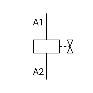
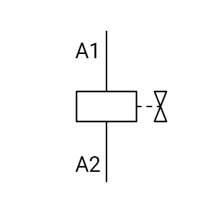
Related Symbols


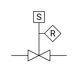
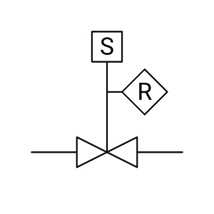
Solenoid with Reset Valve


