Hydraulic Misc
Miscellaneous hydraulic symbols and devices used in hydraulic circuit design
Back to symbols

Sample Drawings
- JIC / NFPA Sample Drawing
- IEC 60617 Sample Drawing
- P&ID PIP Sample Drawing
- Hydraulic Sample Drawing
- Pneumatic Sample Drawing
- ABB
- AC500 PLC COMM INT Modules
- AC500 PLC COMM INT Modules - Layout
- AC500 PLC COMM Modules
- AC500 PLC COMM Modules - Layout
- AC500 PLC Condition Monitoring Modules
- AC500 PLC Condition Monitoring Modules - Layout
- AC500 PLC CPU Modules
- AC500 PLC CPU Modules - Layout
- AC500 S500 PLC AIO Modules
- AC500 S500 PLC AIO Modules - Layout
- AC500 S500 PLC DIO Modules
- AC500 S500 PLC DIO Modules - Layout
- AC500 S500 PLC Special I/O Modules
- AC500 S500 PLC Special I/O Modules - Layout
- AC500-eco PLC AIO Modules
- AC500-eco PLC AIO Modules - Layout
- AC500-eco PLC CPU Modules
- AC500-eco PLC CPU Modules - Layout
- AC500-eco PLC DIO Modules
- AC500-eco PLC DIO Modules - Layout
- AC500-S PLC AIO Modules
- AC500-S PLC AIO Modules - Layout
- AC500-S PLC CPU Modules
- AC500-S PLC CPU Modules - Layout
- AC500-S PLC DIO Modules
- AC500-S PLC DIO Modules - Layout
- AC500-XC PLC AIO Modules
- AC500-XC PLC AIO Modules - Layout
- AC500-XC PLC COMM INT Modules
- AC500-XC PLC COMM INT Modules - Layout
- AC500-XC PLC COMM Modules
- AC500-XC PLC COMM Modules - Layout
- AC500-XC PLC CPU Modules
- AC500-XC PLC CPU Modules - Layout
- AC500-XC PLC DIO Modules
- AC500-XC PLC DIO Modules - Layout
- AC500-XC PLC Special I/O Modules
- AC500-XC PLC Special I/O Modules - Layout
- Automation brands
- Avatars
- Comments
- Computers and Network
- Do-more
- BRX 10 PLC MPU Modules
- BRX 10 PLC MPU Modules - Layout
- BRX 10E PLC MPU Modules
- BRX 10E PLC MPU Modules - Layout
- BRX 18 PLC MPU Modules
- BRX 18 PLC MPU Modules - Layout
- BRX 18E PLC MPU Modules
- BRX 18E PLC MPU Modules - Layout
- BRX 36 PLC MPU Modules
- BRX 36 PLC MPU Modules - Layout
- BRX 36E PLC MPU Modules
- BRX 36E PLC MPU Modules - Layout
- BRX ME PLC MPU Modules
- BRX ME PLC MPU Modules - Layout
- BRX PLC AIO Modules
- BRX PLC AIO Modules - Layout
- BRX PLC COMM Modules
- BRX PLC COMM Modules - Layout
- BRX PLC DIO Modules
- BRX PLC DIO Modules - Layout
- BRX PLC Special Modules
- BRX PLC Special Modules - Layout
- H2 PLC AC I/O Modules
- H2 PLC AC I/O Modules - Layout
- H2 PLC AC/DC I/O Relay Modules
- H2 PLC AC/DC I/O Relay Modules - Layout
- H2 PLC AIO Modules
- H2 PLC AIO Modules - Layout
- H2 PLC COMM Modules
- H2 PLC COMM Modules - Layout
- H2 PLC CPU Modules
- H2 PLC CPU Modules - Layout
- H2 PLC DC I/O Modules
- H2 PLC DC I/O Modules - Layout
- H2 PLC Ethernet Remote Modules
- H2 PLC Ethernet Remote Modules - Layout
- H2 PLC Special Modules
- H2 PLC Special Modules - Layout
- T1H PLC AC I/O Modules
- T1H PLC AC I/O Modules - Layout
- T1H PLC AC/DC I/O Relay Modules
- T1H PLC AC/DC I/O Relay Modules - Layout
- T1H PLC AIO Modules
- T1H PLC AIO Modules - Layout
- T1H PLC CPU Modules
- T1H PLC CPU Modules - Layout
- T1H PLC DC I/O Modules
- T1H PLC DC I/O Modules - Layout
- T1H PLC Power Supply Modules
- T1H PLC Power Supply Modules - Layout
- T1H PLC Special I/O Modules
- T1H PLC Special I/O Modules - Layout
- Electronic Symbols
- Flow Chart
- Gauge and Meters
- Hitachi
- Micro EHV+ PLC AIO Modules
- Micro EHV+ PLC AIO Modules - Layout
- Micro EHV+ PLC Basic Modules
- Micro EHV+ PLC Basic Modules - Layout
- Micro EHV+ PLC DIO Modules
- Micro EHV+ PLC DIO Modules - Layout
- Micro EHV+ PLC RTD Modules
- Micro EHV+ PLC RTD Modules - Layout
- Micro EHV+ PLC Thermocouple Modules - Layout
- Micro EHV+ PLC, Thermocouple Modules
- Honeywell
- ControlEdge PLC AIO Modules
- ControlEdge PLC AIO Modules - Layout
- ControlEdge PLC COMM Modules
- ControlEdge PLC COMM Modules - Layout
- ControlEdge PLC CPU Modules
- ControlEdge PLC CPU Modules - Layout
- ControlEdge PLC DIO Modules
- ControlEdge PLC DIO Modules - Layout
- ControlEdge PLC Power Modules
- ControlEdge PLC Power Modules - Layout
- ControlEdge PLC UIO Modules
- ControlEdge PLC UIO Modules - Layout
- MasterLogic ML200 PLC AIO Modules
- MasterLogic ML200 PLC AIO Modules - Layout
- MasterLogic ML200 PLC COMM Modules
- MasterLogic ML200 PLC COMM Modules - Layout
- MasterLogic ML200 PLC CPU Modules
- MasterLogic ML200 PLC CPU Modules - Layout
- MasterLogic ML200 PLC DIO Modules
- MasterLogic ML200 PLC DIO Modules - Layout
- MasterLogic ML200 PLC Power Modules
- MasterLogic ML200 PLC Power Modules - Layout
- MasterLogic ML50 PLC AIO Modules
- MasterLogic ML50 PLC AIO Modules - Layout
- MasterLogic ML50 PLC Base Modules
- MasterLogic ML50 PLC Base Modules - Layout
- MasterLogic ML50 PLC COMM Modules
- MasterLogic ML50 PLC COMM Modules - Layout
- MasterLogic ML50 PLC DIO Modules
- MasterLogic ML50 PLC DIO Modules - Layout
- Hydraulic
- IEC 60617
- IEC Isolators, Disconnectors, Fuses, Contactors, Overloads
- IEC Power, Meters, Transformers, Motors
- IEC Symbols
- ISO 1219 Fluidic
- JIC / NFPA Symbols
- Koyo
- DirectLOGIC 05/06 PLC AIO Modules
- DirectLOGIC 05/06 PLC AIO Modules - Layout
- DirectLOGIC 05/06 PLC CPU Modules
- DirectLOGIC 05/06 PLC CPU Modules - Layout
- DirectLOGIC 05/06 PLC DIO Modules
- DirectLOGIC 05/06 PLC DIO Modules - Layout
- DirectLOGIC 05/06 PLC Special Modules
- DirectLOGIC 05/06 PLC Special Modules - Layout
- DirectLOGIC 205 PLC AIO Modules
- DirectLOGIC 205 PLC AIO Modules - Layout
- DirectLOGIC 205 PLC CPU Modules
- DirectLOGIC 205 PLC CPU Modules - Layout
- DirectLOGIC 205 PLC DIO Modules
- DirectLOGIC 205 PLC DIO Modules - Layout
- DirectLOGIC 205 PLC Special Modules
- DirectLOGIC 205 PLC Special Modules - Layout
- DirectLOGIC 405 PLC AIO Modules
- DirectLOGIC 405 PLC AIO Modules - Layout
- DirectLOGIC 405 PLC CPU Modules
- DirectLOGIC 405 PLC CPU Modules - Layout
- DirectLOGIC 405 PLC DIO Modules
- DirectLOGIC 405 PLC DIO Modules - Layout
- DirectLOGIC 405 PLC Special Modules
- DirectLOGIC 405 PLC Special Modules - Layout
- KOSTAC SJ PLC AIO Modules
- KOSTAC SJ PLC AIO Modules - Layout
- KOSTAC SJ PLC CPU Modules
- KOSTAC SJ PLC CPU Modules - Layout
- KOSTAC SJ PLC DIO Modules
- KOSTAC SJ PLC DIO Modules - Layout
- KOSTAC SJ PLC Power Modules
- KOSTAC SJ PLC Power Modules - Layout
- Terminator I/O PLC AIO Modules
- Terminator I/O PLC AIO Modules - Layout
- Terminator I/O PLC DIO Modules
- Terminator I/O PLC DIO Modules - Layout
- Terminator I/O PLC Power Modules
- Terminator I/O PLC Power Modules - Layout
- Layout
- Layout 3D
- Measurement tools
- Mitsubishi Electric
- MELSEC iQ-F PLC AIO Modules
- MELSEC iQ-F PLC AIO Modules - Layout
- MELSEC iQ-F PLC COMM Modules
- MELSEC iQ-F PLC COMM Modules - Layout
- MELSEC iQ-F PLC Counter Modules
- MELSEC iQ-F PLC Counter Modules - Layout
- MELSEC iQ-F PLC CPU Modules
- MELSEC iQ-F PLC CPU Modules - Layout
- MELSEC iQ-F PLC DIO Modules
- MELSEC iQ-F PLC DIO Modules - Layout
- MELSEC iQ-F PLC Motion Modules
- MELSEC iQ-F PLC Motion Modules - Layout
- MELSEC iQ-F PLC Pulse Modules
- MELSEC iQ-F PLC Pulse Modules - Layout
- MELSEC iQ-R PLC AIO Modules
- MELSEC iQ-R PLC AIO Modules - Layout
- MELSEC iQ-R PLC COMM Modules
- MELSEC iQ-R PLC COMM Modules - Layout
- MELSEC iQ-R PLC Counter Modules
- MELSEC iQ-R PLC Counter Modules - Layout
- MELSEC iQ-R PLC CPU Modules
- MELSEC iQ-R PLC CPU Modules - Layout
- MELSEC iQ-R PLC DIO Modules
- MELSEC iQ-R PLC DIO Modules - Layout
- MELSEC iQ-R PLC Motion Modules
- MELSEC iQ-R PLC Motion Modules - Layout
- MELSEC iQ-R PLC Positioning Modules
- MELSEC iQ-R PLC Positioning Modules - Layout
- MELSEC iQ-R PLC Pulse Modules
- MELSEC iQ-R PLC Pulse Modules - Layout
- MELSEC iQ-R PLC Technology Modules
- MELSEC iQ-R PLC Technology Modules - Layout
- MELSEC-F FX3G PLC CPU Modules
- MELSEC-F FX3G PLC CPU Modules - Layout
- MELSEC-F FX3GC PLC CPU Modules
- MELSEC-F FX3GC PLC CPU Modules - Layout
- MELSEC-F FX3S PLC CPU Modules
- MELSEC-F FX3S PLC CPU Modules - Layout
- MELSEC-F FX3U PLC CPU Modules
- MELSEC-F FX3U PLC CPU Modules - Layout
- MELSEC-F FX3UC PLC CPU Modules
- MELSEC-F FX3UC PLC CPU Modules - Layout
- MELSEC-F PLC AIO Modules
- MELSEC-F PLC AIO Modules - Layout
- MELSEC-F PLC COMM Modules
- MELSEC-F PLC COMM Modules - Layout
- MELSEC-F PLC Counter Modules
- MELSEC-F PLC Counter Modules - Layout
- MELSEC-F PLC DIO Modules
- MELSEC-F PLC DIO Modules - Layout
- MELSEC-F PLC Positioning Modules
- MELSEC-F PLC Positioning Modules - Layout
- MELSEC-L PLC AIO Modules
- MELSEC-L PLC AIO Modules - Layout
- MELSEC-L PLC COMM Modules
- MELSEC-L PLC COMM Modules - Layout
- MELSEC-L PLC Counter Modules
- MELSEC-L PLC Counter Modules - Layout
- MELSEC-L PLC CPU Modules
- MELSEC-L PLC CPU Modules - Layout
- MELSEC-L PLC DIO Modules
- MELSEC-L PLC DIO Modules - Layout
- MELSEC-L PLC Motion Modules
- MELSEC-L PLC Motion Modules - Layout
- MELSEC-L PLC Positioning Modules
- MELSEC-L PLC Positioning Modules - Layout
- MELSEC-L PLC Power Modules
- MELSEC-L PLC Power Modules - Layout
- MELSEC-Q PLC AIO Modules
- MELSEC-Q PLC AIO Modules - Layout
- MELSEC-Q PLC Counter Modules
- MELSEC-Q PLC Counter Modules - Layout
- MELSEC-Q PLC CPU Modules
- MELSEC-Q PLC CPU Modules - Layout
- MELSEC-Q PLC DIO Modules
- MELSEC-Q PLC DIO Modules - Layout
- MELSEC-Q PLC Motion Modules
- MELSEC-Q PLC Motion Modules - Layout
- MELSEC-Q PLC Positioning Modules
- MELSEC-Q PLC Positioning Modules - Layout
- MELSEC-Q PLC Pulse Modules
- MELSEC-Q PLC Pulse Modules - Layout
- MELSEC-QS PLC COMM Modules
- MELSEC-QS PLC COMM Modules - Layout
- MELSEC-QS PLC CPU Modules
- MELSEC-QS PLC CPU Modules - Layout
- MELSEC-QS PLC Power Modules
- MELSEC-QS PLC Power Modules - Layout
- Omron
- CJ PLC Basic I/O Modules
- CJ PLC Basic I/O Modules - Layout
- CJ PLC COMM Modules
- CJ PLC COMM Modules - Layout
- CJ PLC Interface Modules
- CJ PLC Interface Modules - Layout
- CJ PLC Power Modules
- CJ PLC Power Modules - Layout
- CJ PLC Special Modules
- CJ PLC Special Modules - Layout
- CK3M PLC CPU Modules
- CK3M PLC CPU Modules - Layout
- CK3W PLC AIO Modules
- CK3W PLC AIO Modules - Layout
- CK3W PLC Axial Interface Modules
- CK3W PLC Axial Interface Modules - Layout
- CK3W PLC DIO Modules
- CK3W PLC DIO Modules - Layout
- CK3W PLC Encoder Modules
- CK3W PLC Encoder Modules - Layout
- CK3W PLC Laser Interface Modules
- CK3W PLC Laser Interface Modules - Layout
- CK3W PLC Power Modules
- CK3W PLC Power Modules - Layout
- CP1E PLC E/ES CPU Modules
- CP1E PLC E/ES CPU Modules - Layout
- CP1E PLC N/NA CPU Modules
- CP1E PLC N/NA CPU Modules - Layout
- CP1E PLC NS/NS1 CPU Modules
- CP1E PLC NS/NS1 CPU Modules - Layout
- CP1H PLC CPU Modules
- CP1H PLC CPU Modules - Layout
- CP1L PLC CPU Modules
- CP1L PLC CPU Modules - Layout
- CP1W PLC AIO Modules
- CP1W PLC AIO Modules - Layout
- CP1W PLC COMM Modules
- CP1W PLC COMM Modules - Layout
- CP1W PLC DIO Modules
- CP1W PLC DIO Modules - Layout
- CP1W PLC TEMP Control Modules
- CP1W PLC TEMP Control Modules - Layout
- CP2E PLC CPU Modules
- CP2E PLC CPU Modules - Layout
- CS1 PLC Basic I/O Modules
- CS1 PLC Basic I/O Modules - Layout
- CS1 PLC COMM Modules
- CS1 PLC COMM Modules - Layout
- CS1 PLC Special Modules
- CS1 PLC Special Modules - Layout
- NJ PLC CPU Modules
- NJ PLC CPU Modules - Layout
- NJ PLC Power Modules
- NJ PLC Power Modules - Layout
- NX PLC AIO Modules
- NX PLC AIO Modules - Layout
- NX PLC COMM Modules
- NX PLC COMM Modules - Layout
- NX PLC DIO Modules
- NX PLC DIO Modules - Layout
- NX PLC Load Cell Modules
- NX PLC Load Cell Modules - Layout
- NX PLC Position Modules
- NX PLC Position Modules - Layout
- NX PLC Power Modules
- NX PLC Power Modules - Layout
- NX PLC RFID Modules
- NX PLC RFID Modules - Layout
- NX PLC Safety CPU Modules
- NX PLC Safety CPU Modules - Layout
- NX PLC Safety I/O Modules
- NX PLC Safety I/O Modules - Layout
- NX PLC TEMP Control Modules
- NX PLC TEMP Control Modules - Layout
- NX1 PLC CPU Modules
- NX1 PLC CPU Modules - Layout
- NX1P2 PLC CPU Modules
- NX1P2 PLC CPU Modules - Layout
- NX7 PLC CPU Modules
- NX7 PLC CPU Modules - Layout
- NX7 PLC Power Modules
- NX7 PLC Power Modules - Layout
- P&ID
- P&ID ISO Equipment
- P&ID ISO Fittings
- P&ID ISO Instruments
- P&ID ISO Pipes and Signal Lines
- P&ID ISO Valves
- P&ID PIP Equipment
- P&ID PIP Fittings
- P&ID PIP Instruments
- P&ID PIP Pipes and Signal Lines
- P&ID PIP Valves
- Pneumatic
- Prefab Circuits
- Productivity
- Productivity 1000 PLC AC I/O Relay Modules
- Productivity 1000 PLC AC I/O Relay Modules - Layout
- Productivity 1000 PLC AIO Modules
- Productivity 1000 PLC AIO Modules - Layout
- Productivity 1000 PLC CPU Modules
- Productivity 1000 PLC CPU Modules - Layout
- Productivity 1000 PLC DC & Combo I/O Modules
- Productivity 1000 PLC DC & Combo I/O Modules - Layout
- Productivity 1000 PLC Motion Modules
- Productivity 1000 PLC Motion Modules - Layout
- Productivity 1000 PLC Power Modules
- Productivity 1000 PLC Power Modules - Layout
- Productivity 1000 PLC Special Modules
- Productivity 1000 PLC Special Modules - Layout
- Productivity 2000 PLC AC I/O Relay Modules
- Productivity 2000 PLC AC I/O Relay Modules - Layout
- Productivity 2000 PLC AIO Modules
- Productivity 2000 PLC AIO Modules - Layout
- Productivity 2000 PLC COMM Modules
- Productivity 2000 PLC COMM Modules - Layout
- Productivity 2000 PLC CPU Modules
- Productivity 2000 PLC CPU Modules - Layout
- Productivity 2000 PLC DC I/O Modules
- Productivity 2000 PLC DC I/O Modules - Layout
- Productivity 2000 PLC Motion Modules
- Productivity 2000 PLC Motion Modules - Layout
- Productivity 2000 PLC Power Modules
- Productivity 2000 PLC Power Modules - Layout
- Productivity 2000 PLC Special Modules
- Productivity 2000 PLC Special Modules - Layout
- Productivity 3000 PLC AC I/O Modules
- Productivity 3000 PLC AC I/O Modules - Layout
- Productivity 3000 PLC AIO Modules
- Productivity 3000 PLC AIO Modules - Layout
- Productivity 3000 PLC COMM Modules
- Productivity 3000 PLC COMM Modules - Layout
- Productivity 3000 PLC CPU Modules
- Productivity 3000 PLC CPU Modules - Layout
- Productivity 3000 PLC DC I/O Modules
- Productivity 3000 PLC DC I/O Modules - Layout
- Productivity 3000 PLC Power Modules
- Productivity 3000 PLC Power Modules - Layout
- Productivity 3000 PLC Special Modules
- Productivity 3000 PLC Special Modules - Layout
- Reports
- Siemens
- LOGO! PLC AIO Modules
- LOGO! PLC AIO Modules - Layout
- LOGO! PLC COMM Modules
- LOGO! PLC COMM Modules - Layout
- LOGO! PLC CPU Modules
- LOGO! PLC CPU Modules - Layout
- LOGO! PLC DIO Modules
- LOGO! PLC DIO Modules - Layout
- LOGO! PLC Power Modules
- LOGO! PLC Power Modules - Layout
- SIMATIC ET200AL PLC AIO Modules
- SIMATIC ET200AL PLC AIO Modules - Layout
- SIMATIC ET200AL PLC DIO Modules
- SIMATIC ET200AL PLC DIO Modules - Layout
- SIMATIC ET200AL PLC Fail-safe Modules
- SIMATIC ET200AL PLC Fail-safe Modules - Layout
- SIMATIC ET200AL PLC Interface Modules
- SIMATIC ET200AL PLC Interface Modules - Layout
- SIMATIC ET200AL PLC IO Link I/O Modules
- SIMATIC ET200AL PLC IO Link I/O Modules - Layout
- SIMATIC ET200ECO PN PLC AIO Modules
- SIMATIC ET200ECO PN PLC AIO Modules - Layout
- SIMATIC ET200ECO PN PLC DIO Modules
- SIMATIC ET200ECO PN PLC DIO Modules - Layout
- SIMATIC ET200ECO PN PLC Fail-safe Modules
- SIMATIC ET200ECO PN PLC Fail-safe Modules - Layout
- SIMATIC ET200ECO PN PLC IO Link Master Modules
- SIMATIC ET200ECO PN PLC IO Link Master Modules - Layout
- SIMATIC ET200iSP PLC AIO Modules
- SIMATIC ET200iSP PLC AIO Modules - Layout
- SIMATIC ET200iSP PLC COMM Modules - Layout
- SIMATIC ET200iSP PLC DIO Modules
- SIMATIC ET200iSP PLC DIO Modules - Layout
- SIMATIC ET200iSP PLC Fail-safe Modules
- SIMATIC ET200iSP PLC Fail-safe Modules - Layout
- SIMATIC ET200iSP PLC Interface Modules
- SIMATIC ET200iSP PLC Interface Modules - Layout
- SIMATIC ET200iSP PLC Power Modules
- SIMATIC ET200iSP PLC Power Modules - Layout
- SIMATIC ET200iSP PLC, COMM Modules
- SIMATIC ET200M PLC Interface Modules
- SIMATIC ET200M PLC Interface Modules - Layout
- SIMATIC ET200MP PLC Interface Modules
- SIMATIC ET200MP PLC Interface Modules - Layout
- SIMATIC ET200MP PLC Power Modules
- SIMATIC ET200MP PLC Power Modules - Layout
- SIMATIC ET200pro PLC AIO Modules
- SIMATIC ET200pro PLC AIO Modules - Layout
- SIMATIC ET200pro PLC COMM Modules
- SIMATIC ET200pro PLC COMM Modules - Layout
- SIMATIC ET200pro PLC CPU Modules
- SIMATIC ET200pro PLC CPU Modules - Layout
- SIMATIC ET200pro PLC DIO Modules
- SIMATIC ET200pro PLC DIO Modules - Layout
- SIMATIC ET200pro PLC Fail-safe Modules
- SIMATIC ET200pro PLC Fail-safe Modules - Layout
- SIMATIC ET200pro PLC Interface Modules
- SIMATIC ET200pro PLC Interface Modules - Layout
- SIMATIC ET200pro PLC Power Modules
- SIMATIC ET200pro PLC Power Modules - Layout
- SIMATIC ET200S PLC AIO Modules
- SIMATIC ET200S PLC AIO Modules - Layout
- SIMATIC ET200S PLC CPU Modules
- SIMATIC ET200S PLC CPU Modules - Layout
- SIMATIC ET200S PLC DIO Modules
- SIMATIC ET200S PLC DIO Modules - Layout
- SIMATIC ET200S PLC Fail-safe Modules
- SIMATIC ET200S PLC Fail-safe Modules - Layout
- SIMATIC ET200S PLC POT DIS Modules
- SIMATIC ET200S PLC POT DIS Modules - Layout
- SIMATIC ET200S PLC Power Modules
- SIMATIC ET200S PLC Power Modules - Layout
- SIMATIC ET200S PLC Technology Modules
- SIMATIC ET200S PLC Technology Modules - Layout
- SIMATIC ET200SP HA PLC AIO Modules
- SIMATIC ET200SP HA PLC AIO Modules - Layout
- SIMATIC ET200SP HA PLC AIO/DIO Modules
- SIMATIC ET200SP HA PLC AIO/DIO Modules - Layout
- SIMATIC ET200SP HA PLC DIO Modules
- SIMATIC ET200SP HA PLC DIO Modules - Layout
- SIMATIC ET200SP HA PLC EX I/O Modules
- SIMATIC ET200SP HA PLC EX I/O Modules - Layout
- SIMATIC ET200SP HA PLC Fail-safe I/O Modules
- SIMATIC ET200SP HA PLC Fail-safe I/O Modules - Layout
- SIMATIC ET200SP HA PLC Interface Modules
- SIMATIC ET200SP HA PLC Interface Modules - Layout
- SIMATIC ET200SP PLC AIO Modules
- SIMATIC ET200SP PLC AIO Modules - Layout
- SIMATIC ET200SP PLC COMM Modules
- SIMATIC ET200SP PLC COMM Modules - Layout
- SIMATIC ET200SP PLC CPU Modules
- SIMATIC ET200SP PLC CPU Modules - Layout
- SIMATIC ET200SP PLC DIO Modules
- SIMATIC ET200SP PLC DIO Modules - Layout
- SIMATIC ET200SP PLC DRIVE Modules
- SIMATIC ET200SP PLC DRIVE Modules - Layout
- SIMATIC ET200SP PLC Fail-safe Modules
- SIMATIC ET200SP PLC Fail-safe Modules - Layout
- SIMATIC ET200SP PLC Power Modules
- SIMATIC ET200SP PLC Power Modules - Layout
- SIMATIC ET200SP PLC TECH Modules - Layout
- SIMATIC ET200SP PLC, TECH Modules
- SIMATIC S7-1200 PLC AIO Modules
- SIMATIC S7-1200 PLC AIO Modules - Layout
- SIMATIC S7-1200 PLC COMM Modules
- SIMATIC S7-1200 PLC COMM Modules - Layout
- SIMATIC S7-1200 PLC CPU Modules
- SIMATIC S7-1200 PLC CPU Modules - Layout
- SIMATIC S7-1200 PLC DIO Modules
- SIMATIC S7-1200 PLC DIO Modules - Layout
- SIMATIC S7-1200 PLC Power Modules
- SIMATIC S7-1200 PLC Power Modules - Layout
- SIMATIC S7-1200 PLC Special Modules
- SIMATIC S7-1200 PLC Special Modules - Layout
- SIMATIC S7-1500 CPU Modules
- SIMATIC S7-1500 PLC AIO Modules
- SIMATIC S7-1500 PLC AIO Modules - Layout
- SIMATIC S7-1500 PLC COMM Modules
- SIMATIC S7-1500 PLC COMM Modules - Layout
- SIMATIC S7-1500 PLC CPU Modules - Layout
- SIMATIC S7-1500 PLC DIO Modules
- SIMATIC S7-1500 PLC DIO Modules - Layout
- SIMATIC S7-1500 PLC Fail-safe Modules
- SIMATIC S7-1500 PLC Fail-safe Modules - Layout
- SIMATIC S7-1500 PLC Power Modules
- SIMATIC S7-1500 PLC Power Modules - Layout
- SIMATIC S7-1500 PLC TECH Modules
- SIMATIC S7-1500 PLC TECH Modules - Layout
- SIMATIC S7-200 PLC AIO Modules
- SIMATIC S7-200 PLC AIO Modules - Layout
- SIMATIC S7-200 PLC COMM Modules
- SIMATIC S7-200 PLC COMM Modules - Layout
- SIMATIC S7-200 PLC CPU Modules
- SIMATIC S7-200 PLC CPU Modules - Layout
- SIMATIC S7-200 PLC DIO Modules
- SIMATIC S7-200 PLC DIO Modules - Layout
- SIMATIC S7-200 PLC Positioning Modules
- SIMATIC S7-200 PLC Positioning Modules - Layout
- SIMATIC S7-300 PLC AIO Modules
- SIMATIC S7-300 PLC AIO Modules - Layout
- SIMATIC S7-300 PLC COMM Modules
- SIMATIC S7-300 PLC COMM Modules - Layout
- SIMATIC S7-300 PLC CPU Modules
- SIMATIC S7-300 PLC CPU Modules - Layout
- SIMATIC S7-300 PLC DIO Modules
- SIMATIC S7-300 PLC DIO Modules - Layout
- SIMATIC S7-300 PLC Ex AIO Modules
- SIMATIC S7-300 PLC Ex AIO Modules - Layout
- SIMATIC S7-300 PLC Ex DIO Modules
- SIMATIC S7-300 PLC Ex DIO Modules - Layout
- SIMATIC S7-300 PLC F-DIO/AIO Modules
- SIMATIC S7-300 PLC F-DIO/AIO Modules - Layout
- SIMATIC S7-300 PLC Function Modules
- SIMATIC S7-300 PLC Function Modules - Layout
- SIMATIC S7-300 PLC Power Modules
- SIMATIC S7-300 PLC Power Modules - Layout
- SIMATIC S7-300 PLC Special Modules
- SIMATIC S7-300 PLC Special Modules - Layout
- SIMATIC S7-400 PLC AIO Modules
- SIMATIC S7-400 PLC AIO Modules - Layout
- SIMATIC S7-400 PLC COMM Modules
- SIMATIC S7-400 PLC COMM Modules - Layout
- SIMATIC S7-400 PLC CPU Modules
- SIMATIC S7-400 PLC CPU Modules - Layout
- SIMATIC S7-400 PLC DIO Modules
- SIMATIC S7-400 PLC DIO Modules - Layout
- SIMATIC S7-400 PLC Function Modules
- SIMATIC S7-400 PLC Function Modules - Layout
- SIMATIC S7-400 PLC Interface Modules
- SIMATIC S7-400 PLC Interface Modules - Layout
- SIMATIC S7-400 PLC Power Modules
- SIMATIC S7-400 PLC Power Modules - Layout
- Single Line Symbols
- Title blocks
- Wires
Stencils
Categories
- announciators
- auxilliary contacts
- batteries
- brakes & clutches
- cam switches
- capacitors
- circuit breakers
- connectors
- contactors
- counters
- diacs & triacs
- diodes
- disconnectors
- emergency switches
- flow sensors
- foot switches
- fuses
- heaters
- home and building
- hydraulic miscellaneous
- inductors
- layout
- level sensors
- limit switches
- meters
- miscellaneous
- motors
- optocouplers
- overload trips
- panels
- photoelectric sensors
- P&ID
- pilot lights
- pneumatic miscellaneous
- power supplies
- Prefabricated circuits
- Pressure sensors
- Programmable Logic Controllers (PLC)
- proximity sensors
- pull buttons
- push buttons
- relays
- resistors
- selector switches
- solenoid valves
- temperature sensors & controllers
- terminal block
- thermistors
- timers
- transformers
- transistors
")
")


")
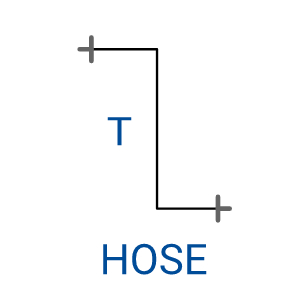
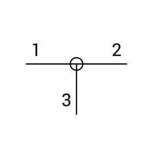
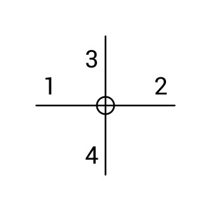
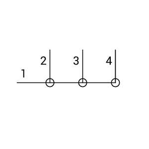
Hose - Mid, with Jump (horizontal)
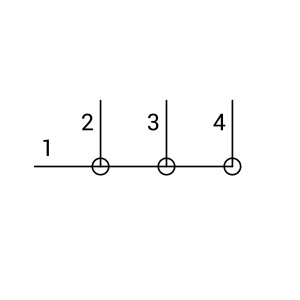
Hose - Mid, with Jump (horizontal)
Hose - Mid, with Jump (horizontal)
")


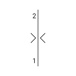
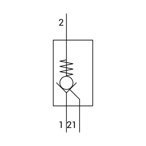
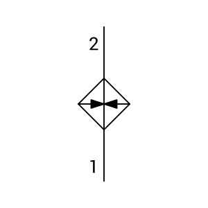
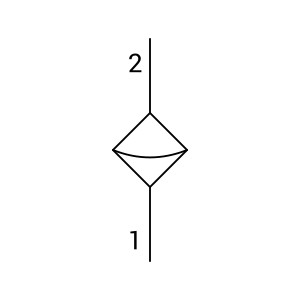
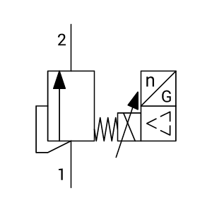
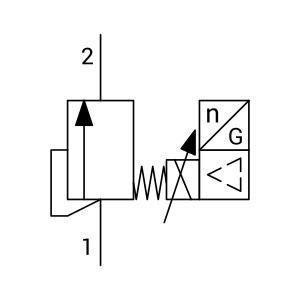
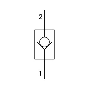
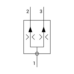
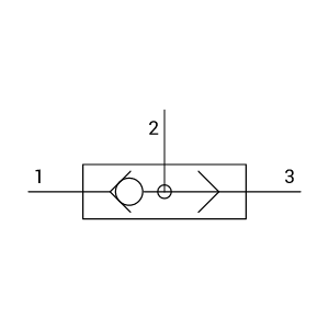
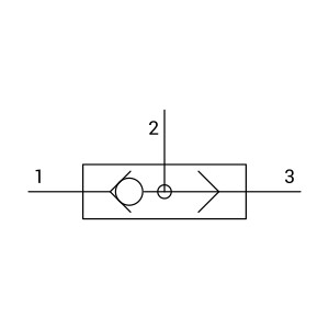
Piloted Non-return Valve w Spring
Piloted Non-return Valve with Spring
H1
Hydraulic Piloted Non-return Valve with Spring
Piloted Non-return Valve w Spring


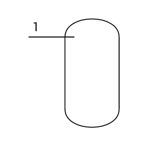
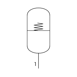
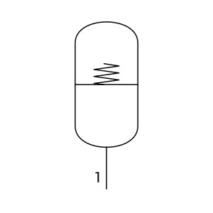
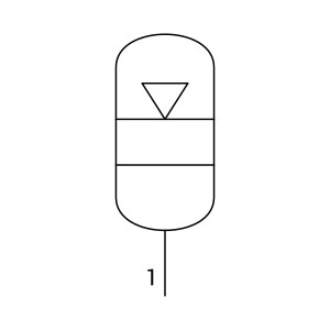
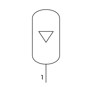
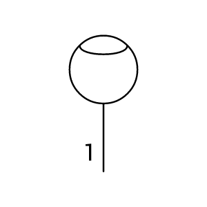
Accumulator w Spring Loaded

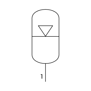
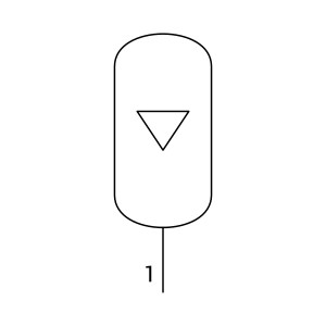
Accumulator w Gas Charged

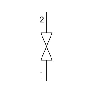
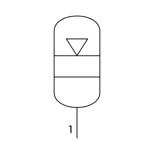
Gas Pressure Accumulator, Piston
Gas Pressure Accumulator, Piston
H1
Hydraulic Gas Pressure Accumulator, Piston
Gas Pressure Accumulator, Piston

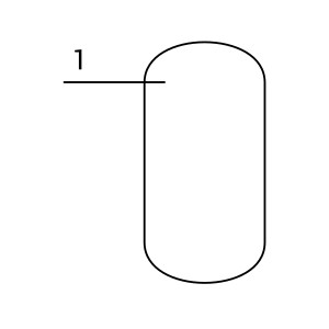
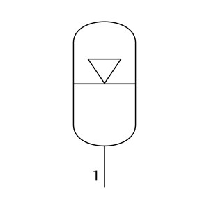
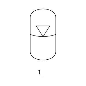
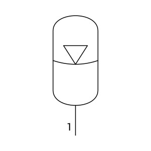
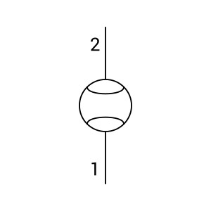
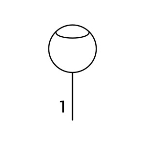
Gas Pressure Accumulator, Bladder
Gas Pressure Accumulator, Bladder
H1
Hydraulic Gas Pressure Accumulator, Bladder
Gas Pressure Accumulator, Bladder


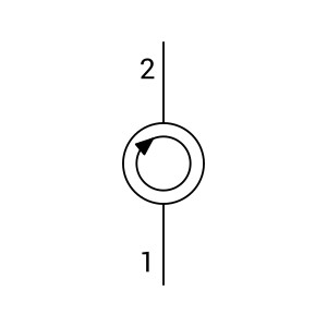
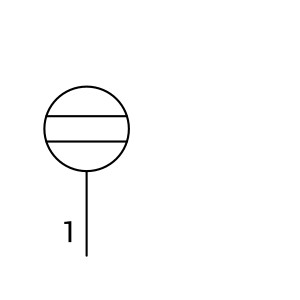
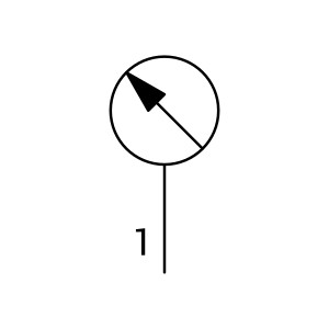
Fluid Level Switch


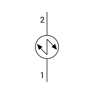
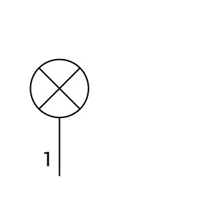
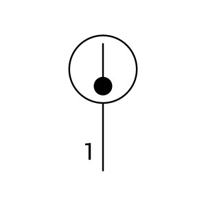
Temperature Controller


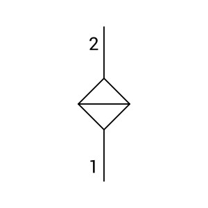
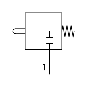
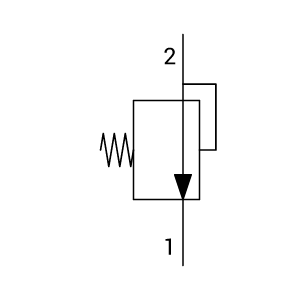
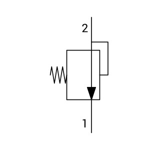
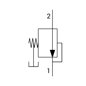
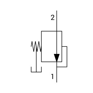
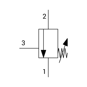
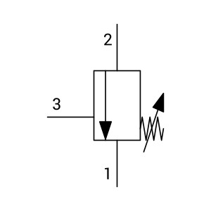
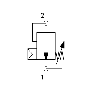
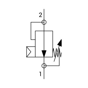
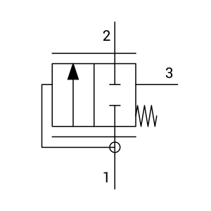
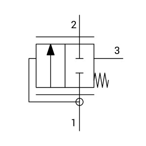
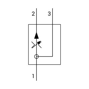
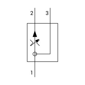
Pressure Reducing Valve

Pressure Reducing Valve, Direct, Control Oil Discharge
Pressure Reducing Valve, Direct, Control Oil Discharge
H1
Hydraulic Pressure Reducing Valve, Direct, Control Oil Discharge
Pressure Reducing Valve, Direct, Control Oil Discharge

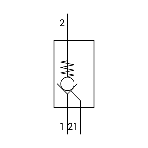
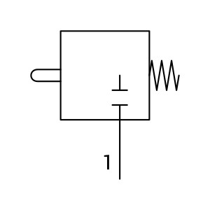
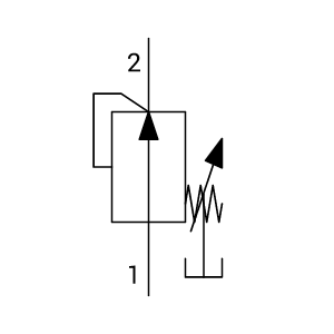
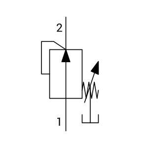
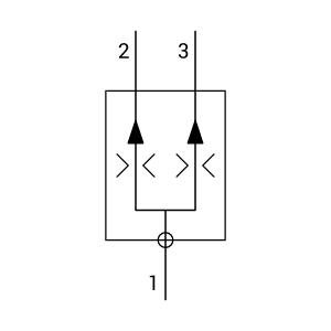
Shut-off Counterbalancing Valve
Shut-off Counterbalancing Valve
H1
Hydraulic Shut-off Counterbalancing Valve
Shut-off Counterbalancing Valve

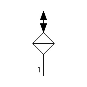
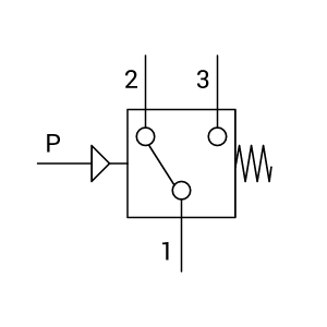
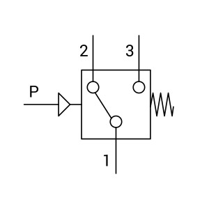
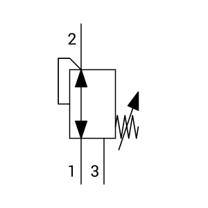
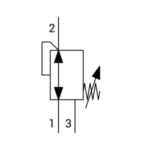
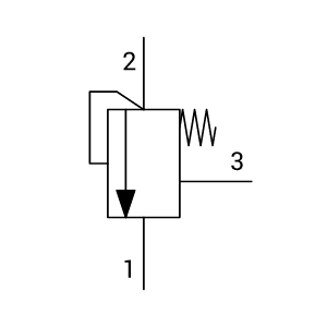
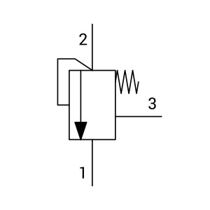
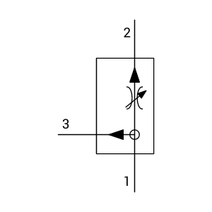
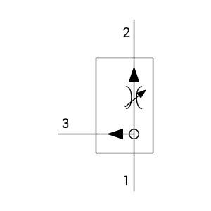
Three-way Pressure Reduction Valve
Three-way Pressure Reduction Valve
H1
Hydraulic Three-way Pressure Reduction Valve
Three-way Pressure Reduction Valve

Accumulator Charging Valve

Pressure Compensator, Open Centre Load Sensing
Pressure Compensator, Open Centre Load Sensing
H1
Hydraulic Pressure Compensator, Open Centre Load Sensing
Pressure Compensator, Open Centre Load Sensing

Pressure Relief, Direct, Position Control, Electronics
Pressure Relief, Direct, Position Control, Electronics
H1
Hydraulic Pressure Relief, Direct, Position Control, Electronics
Pressure Relief, Direct, Position Control, Electronics

Pressure Compensator, Downstream
Pressure Compensator, Downstream
H1
Hydraulic Pressure Compensator, Downstream
Pressure Compensator, Downstream


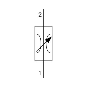
Adjustable Two-way Flow Control
Adjustable Two-way Flow Control
H1
Hydraulic Adjustable Two-way Flow Control
Adjustable Two-way Flow Control

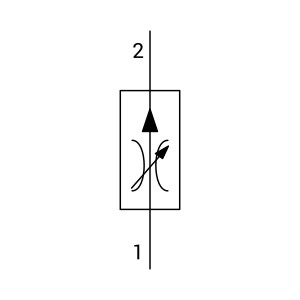
Three-way Flow Control

Adjustable Three-way Flow Control
Adjustable Three-way Flow Control
H1
Hydraulic Adjustable Three-way Flow Control
Adjustable Three-way Flow Control


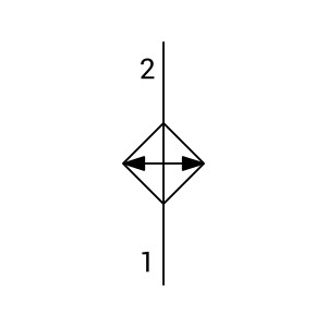
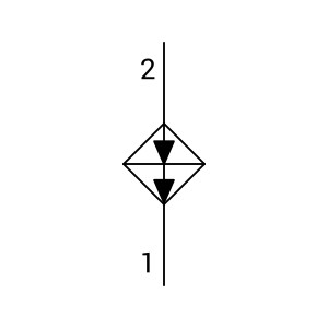
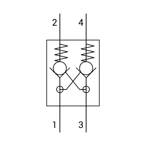
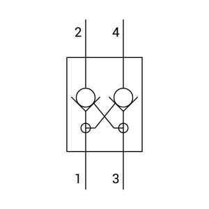
Double Non-return Valve, Delockable
Double Non-return Valve, Delockable
H1
Hydraulic Double Non-return Valve, Delockable
Double Non-return Valve, Delockable

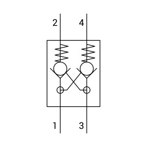
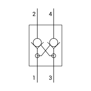
Double Non-return Valve, Piloted
Double Non-return Valve, Piloted
H1
Hydraulic Double Non-return Valve, Piloted


